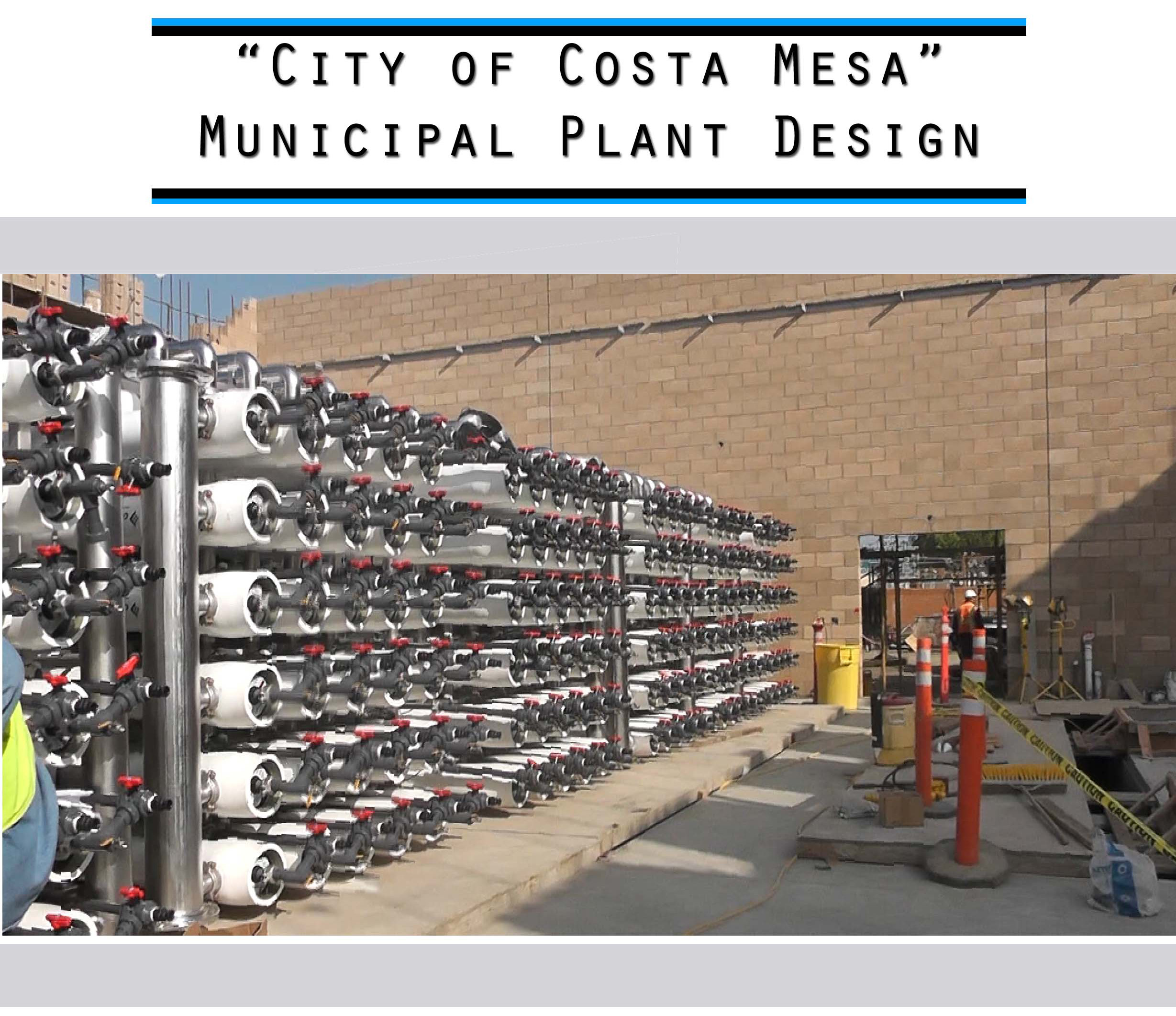
Costa Mesa Municipal
Water Treatment Facility
Autodesk Inventor Mechanical Design Drawings — Municipal Water Treatment
A comprehensive fabrication drawing package developed in Autodesk Inventor for the Costa Mesa Municipal water treatment facility. The drawing set covers the full system scope — from Train 1(A) general arrangement and 1st/2nd stage RO assemblies through frame details, pipe spools, sampling stations, and the nanofiltration system.
/page04-05Large.jpg)
The Train 1(A) general arrangement drawings establish the overall layout and equipment configuration for the Costa Mesa Municipal water treatment system. Developed in Autodesk Inventor, these 7 sheets document the primary skid assembly, vessel positioning, and interconnection routing required for system fabrication and installation.
/page06-07Large.jpg)
/page08-09Large.jpg)
/page10-11Large.jpg)
/page12-13Large.jpg)
/page14-15Large.jpg)
/page16-17Large.jpg)
-A Hardware LOC/page18-19Large.jpg)
The hardware location drawings identify the placement and specification of mechanical components, mounting hardware, and instrument connections for Train 1(A) of the Costa Mesa system. These 4 sheets provide the procurement and installation references for all hardware items on the train.
-A Hardware LOC/page20-21Large.jpg)
-A Hardware LOC/page22-23Large.jpg)
-A Hardware LOC/page24-25Large.jpg)
 1st Stage Assy X/page26-27Large.jpg)
The 1st Stage Assembly X drawings detail the membrane vessel arrangement, interconnecting headers, and port connections for the X-axis orientation of the first RO stage. These 6 sheets provide the dimensional and spatial references required for precise field assembly.
 1st Stage Assy X/page28-29Large.jpg)
 1st Stage Assy X/page30-31Large.jpg)
 1st Stage Assy X/page32-33Large.jpg)
 1st Stage Assy X/page34-35Large.jpg)
 1st Stage Assy X/page36-37Large.jpg)
 1st Stage Assy Y/page38-39Large.jpg)
The 1st Stage Assembly Y drawings document the Y-axis membrane vessel layout, permeate and concentrate manifolds, and support structure connections for the first RO stage. These 6 sheets complement the Assy X set to fully define the 1st stage array.
 1st Stage Assy Y/page40-41Large.jpg)
 1st Stage Assy Y/page42-43Large.jpg)
 1st Stage Assy Y/page44-45Large.jpg)
 1st Stage Assy Y/page46-47Large.jpg)
 1st Stage Assy Y/page48-49Large.jpg)
 2nd Stage/page50-51Large.jpg)
The 2nd Stage drawings define the second-pass reverse osmosis membrane array for Train 1(A), documenting vessel placement, manifold routing, and structural support details. These 6 sheets provide the fabrication basis for the concentration stage of the Costa Mesa treatment system.
 2nd Stage/page52-53Large.jpg)
 2nd Stage/page54-55Large.jpg)
 2nd Stage/page56-57Large.jpg)
 2nd Stage/page58-59Large.jpg)
 2nd Stage/page60-61Large.jpg)
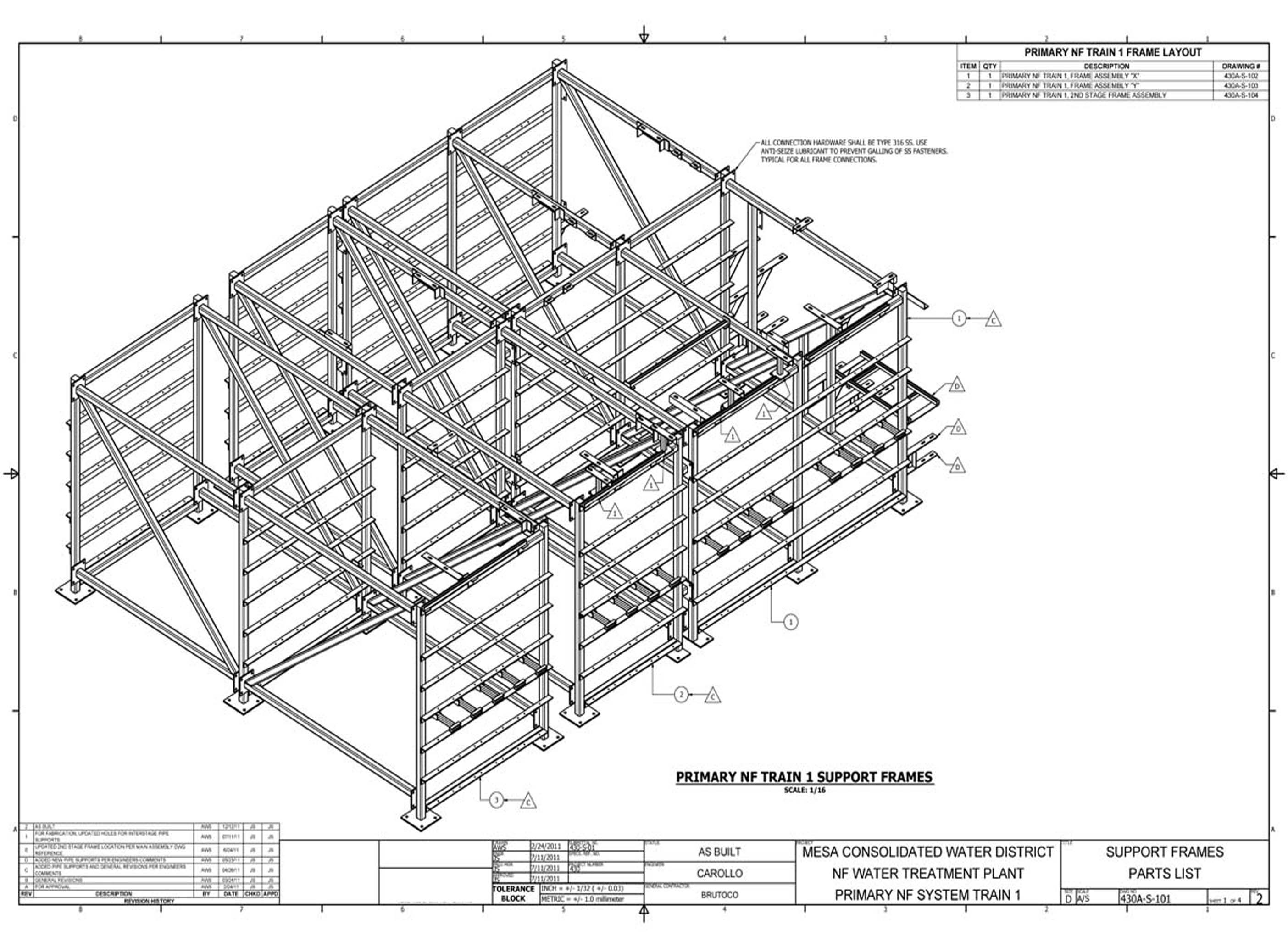
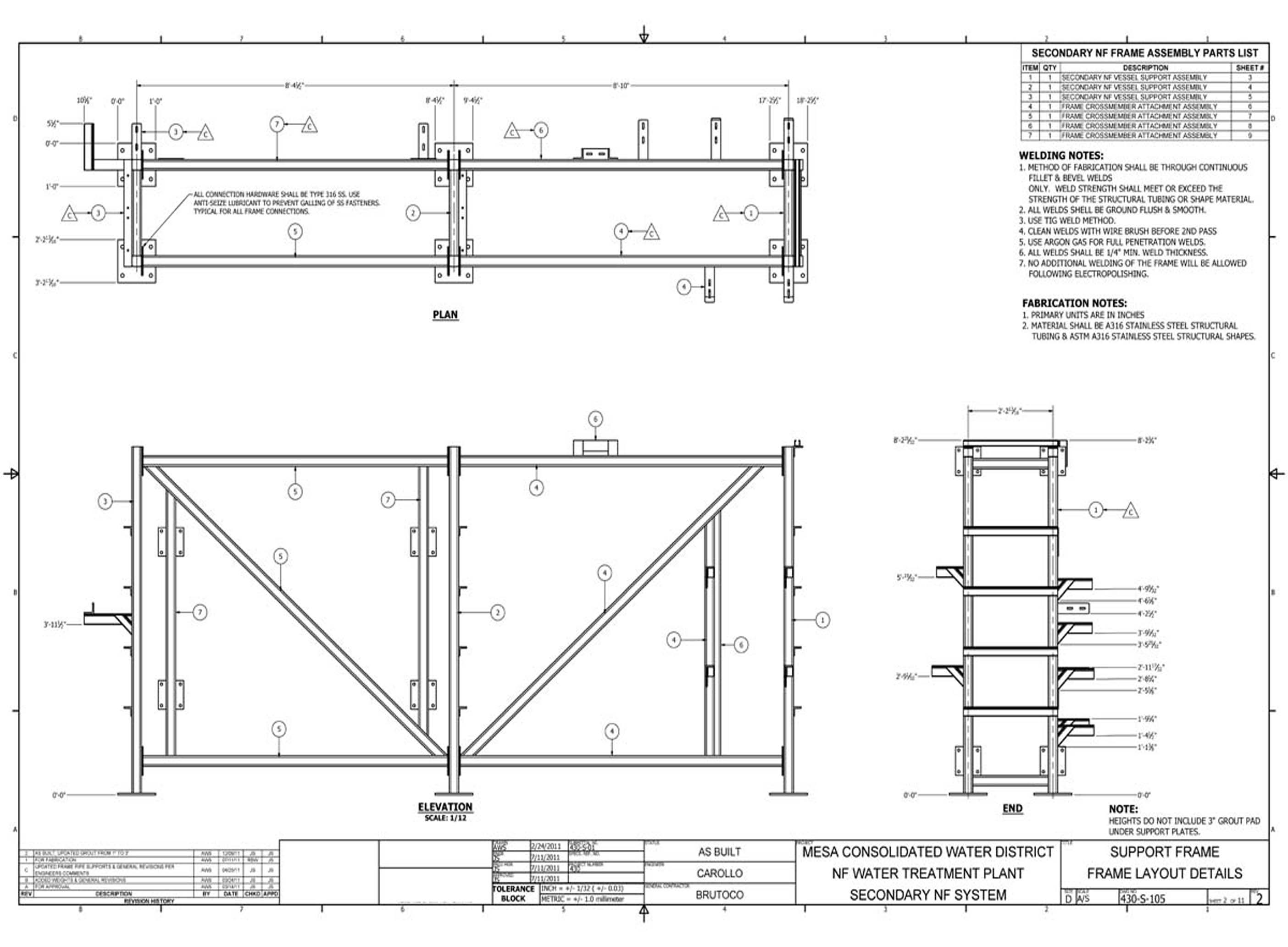
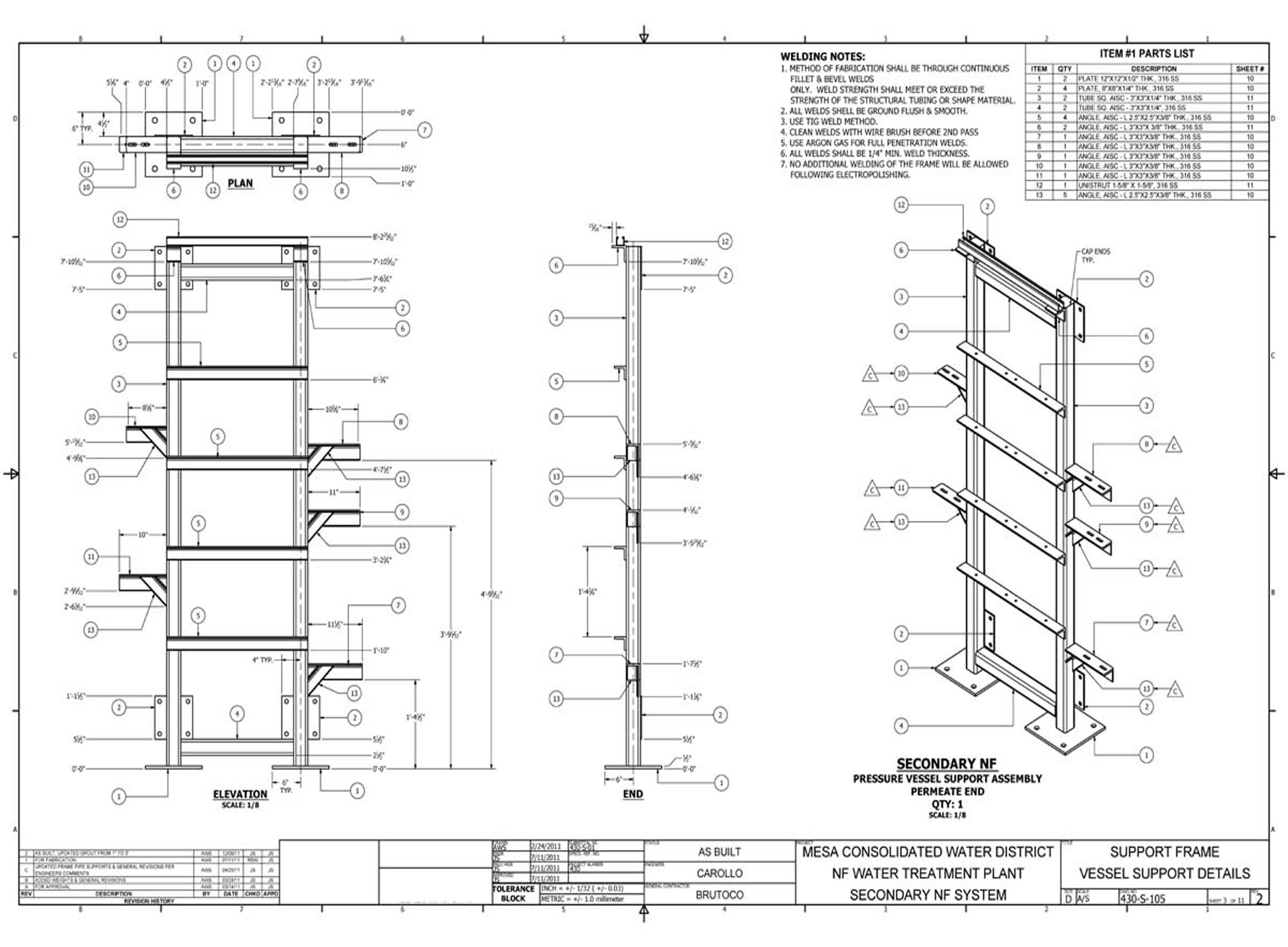
The frame detail drawings document the structural framing assemblies, connection details, and dimensional specifications for the Costa Mesa Municipal water treatment facility. These 18 sheets provide the primary fabrication references for all structural frame components.
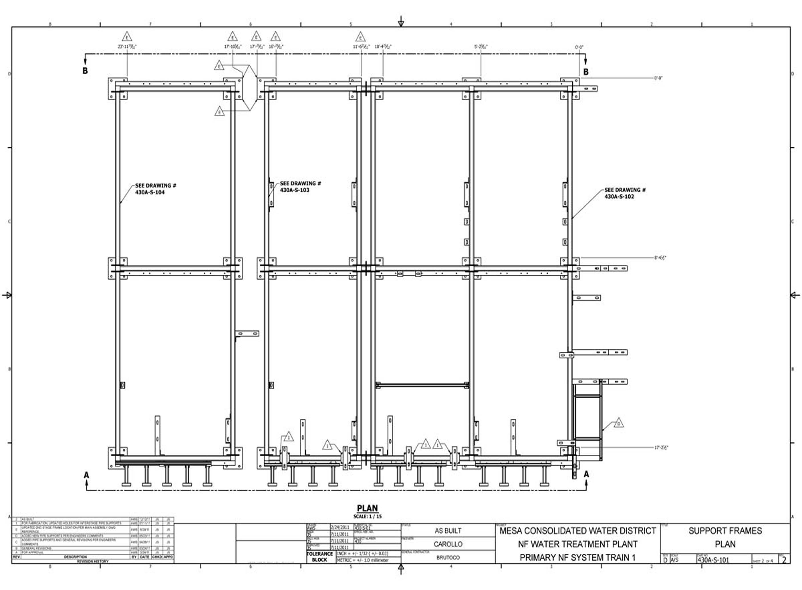
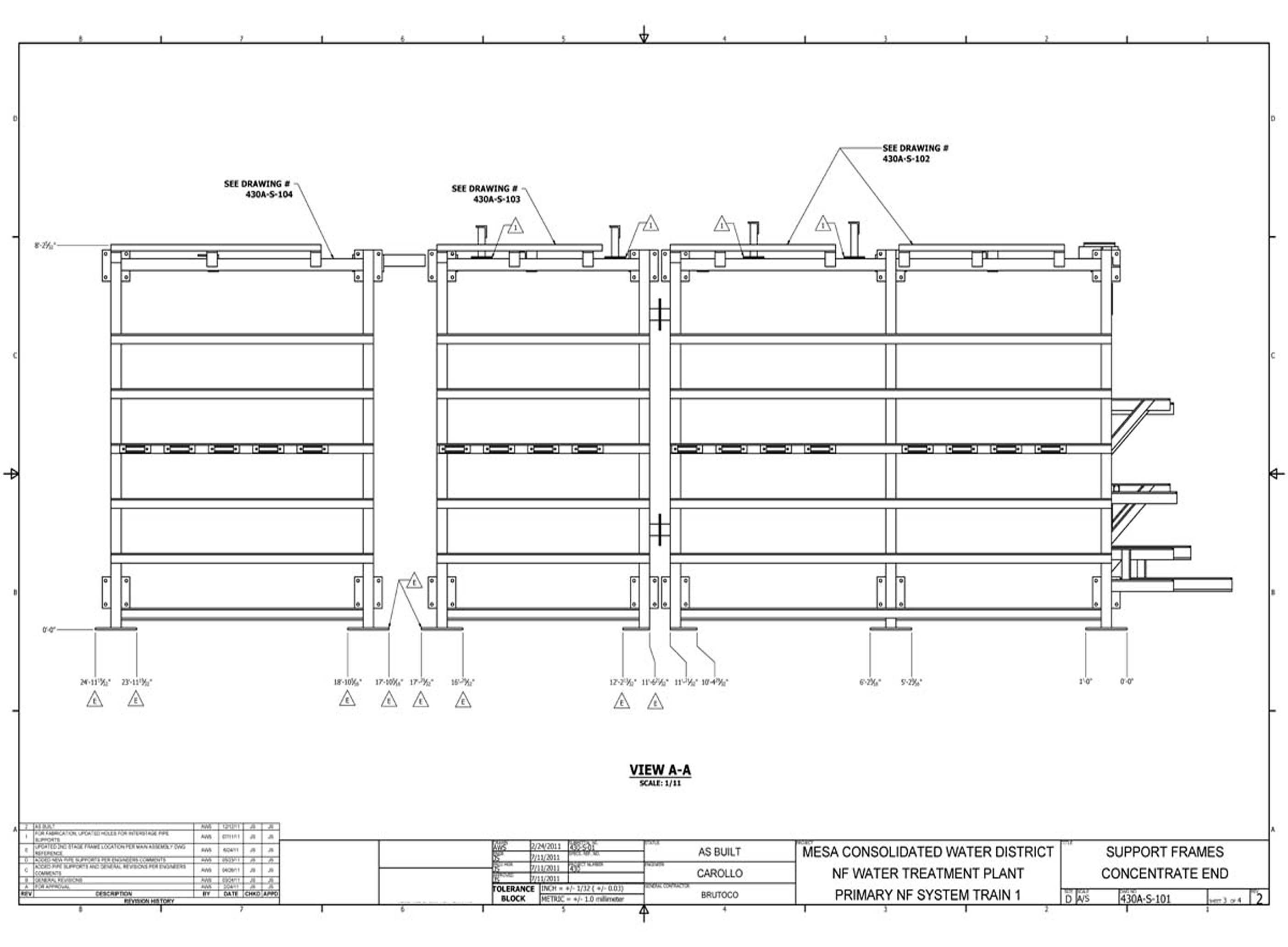
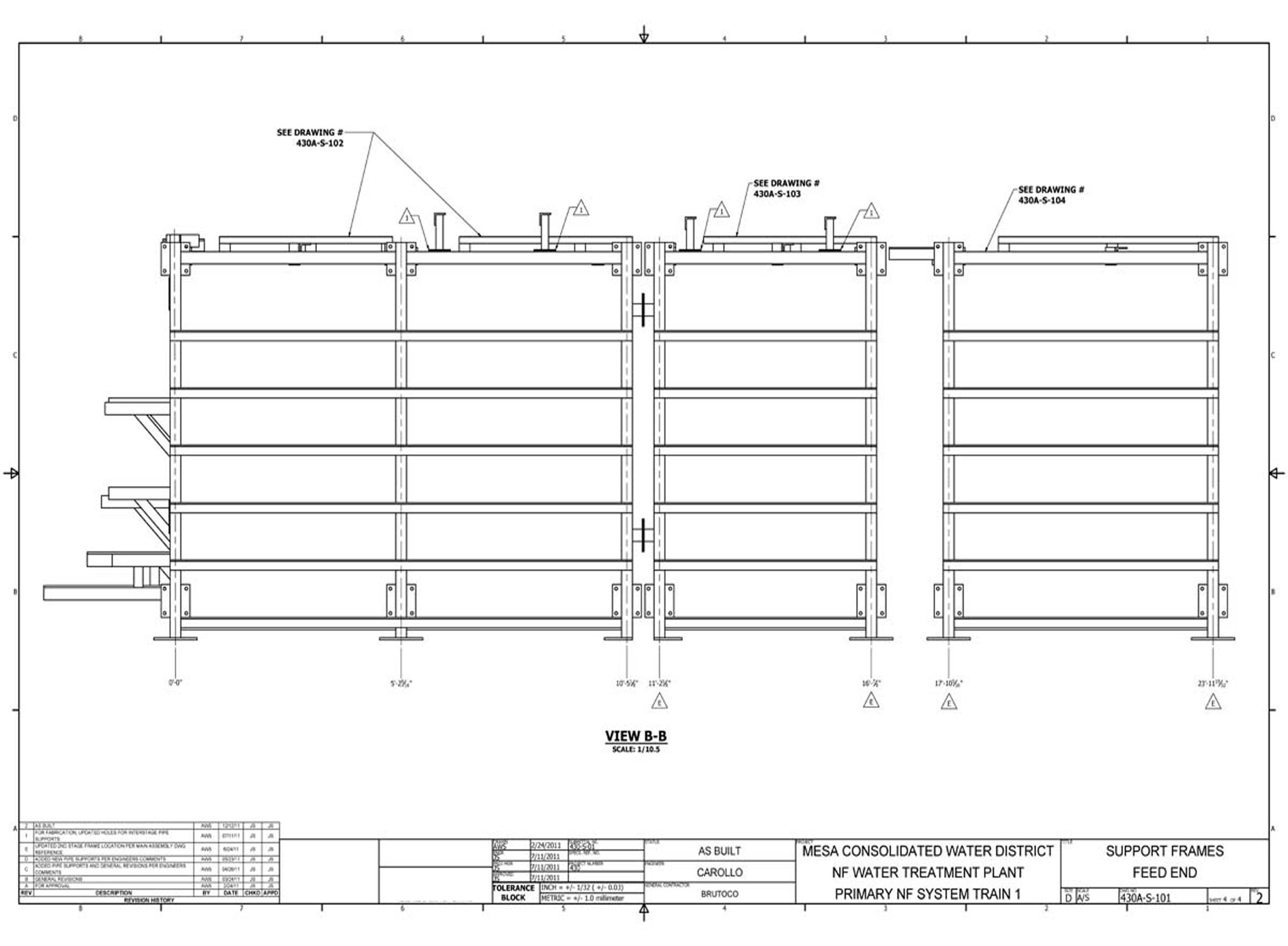
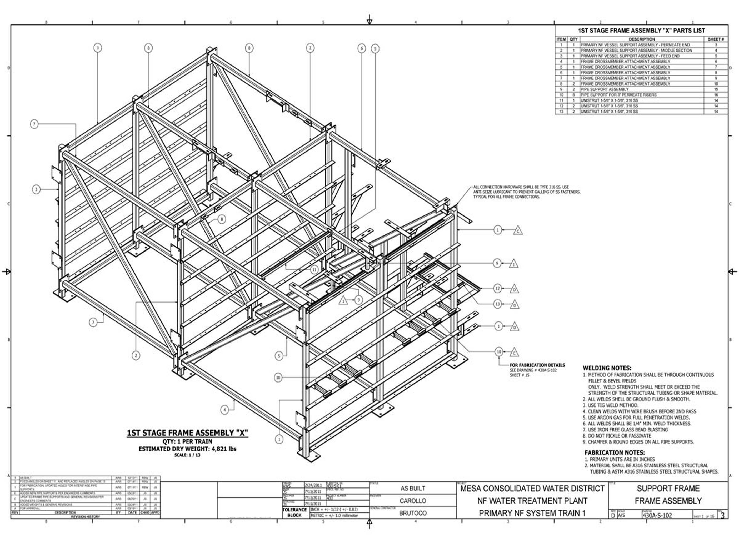
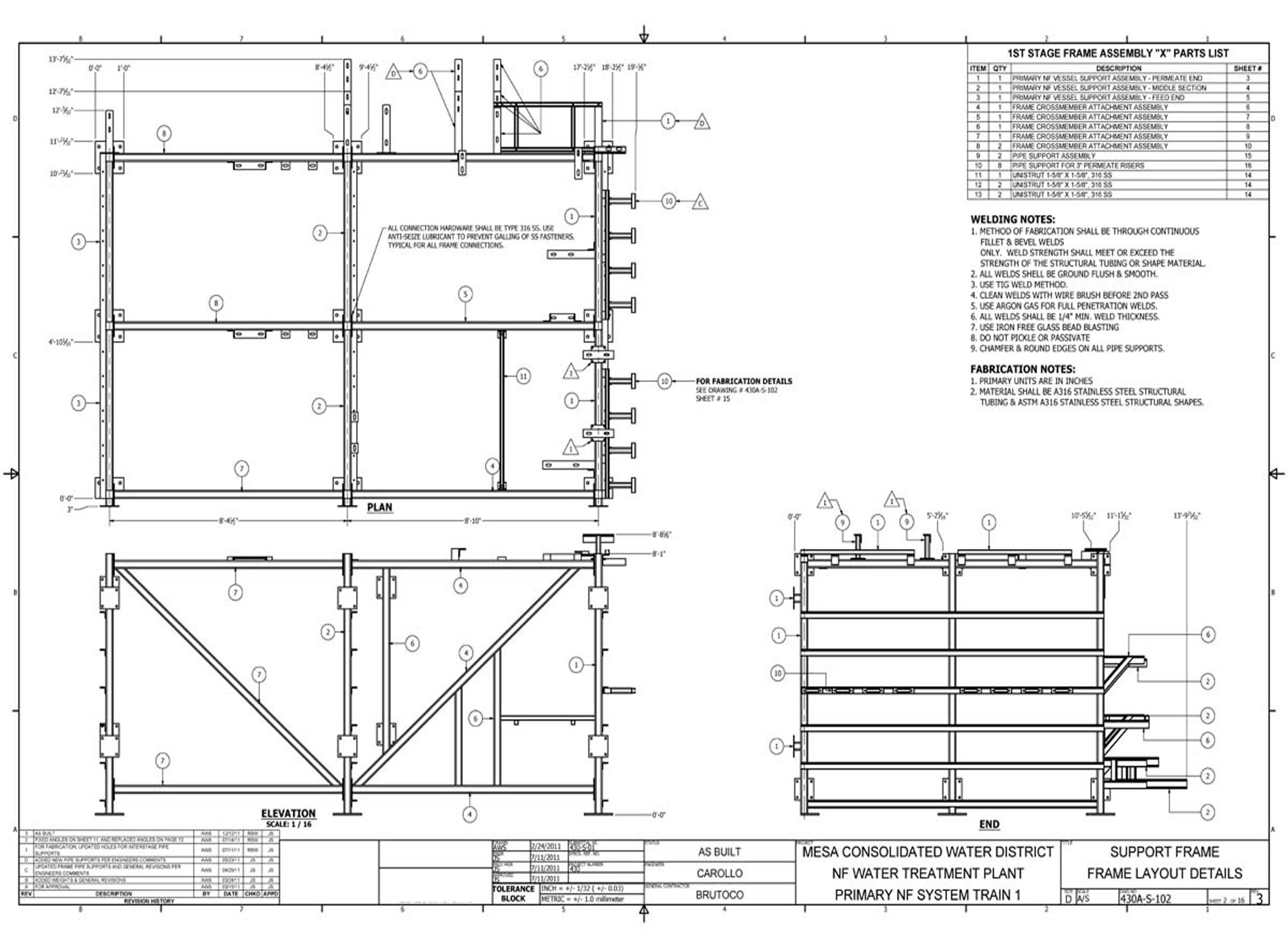
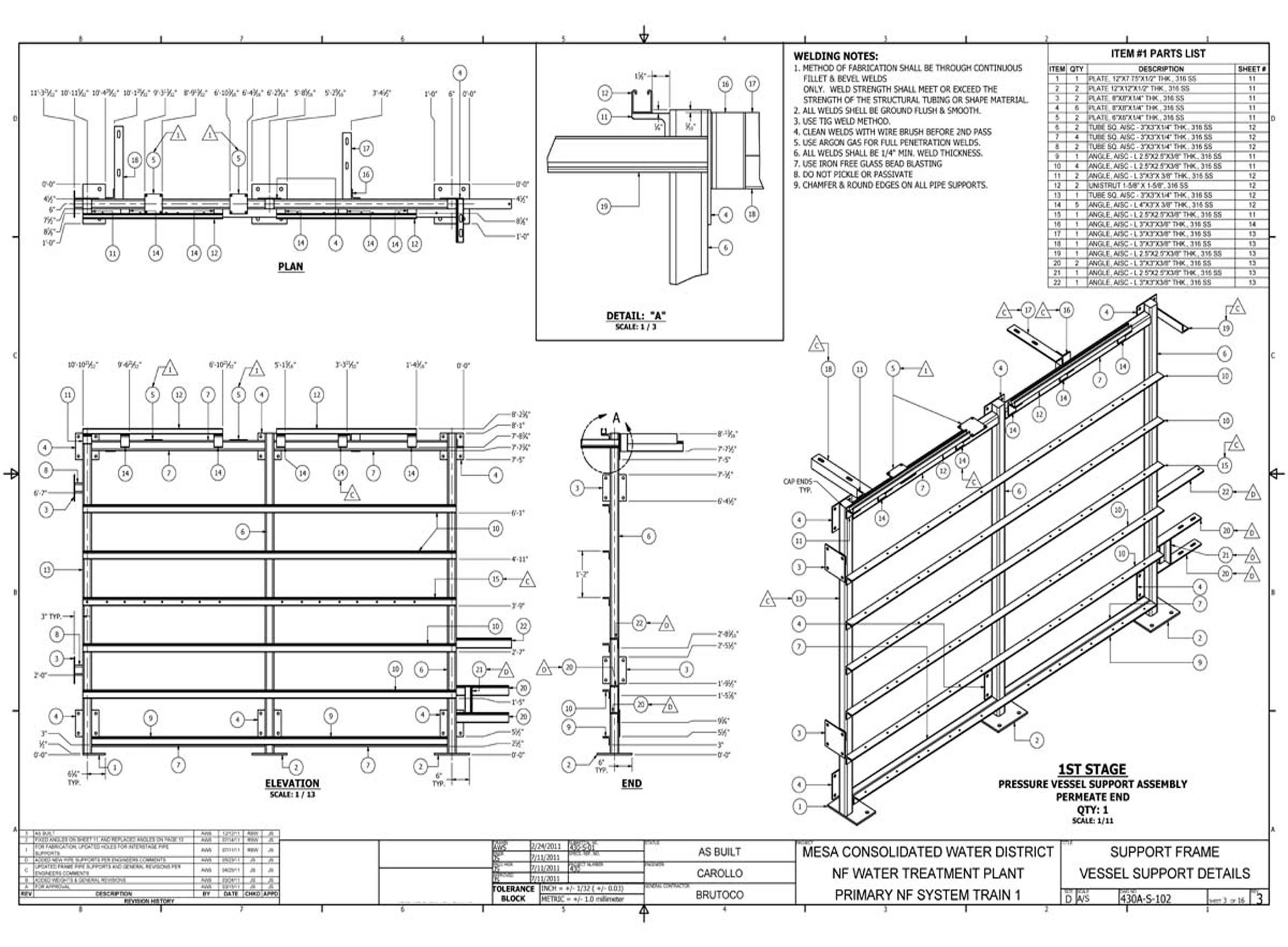
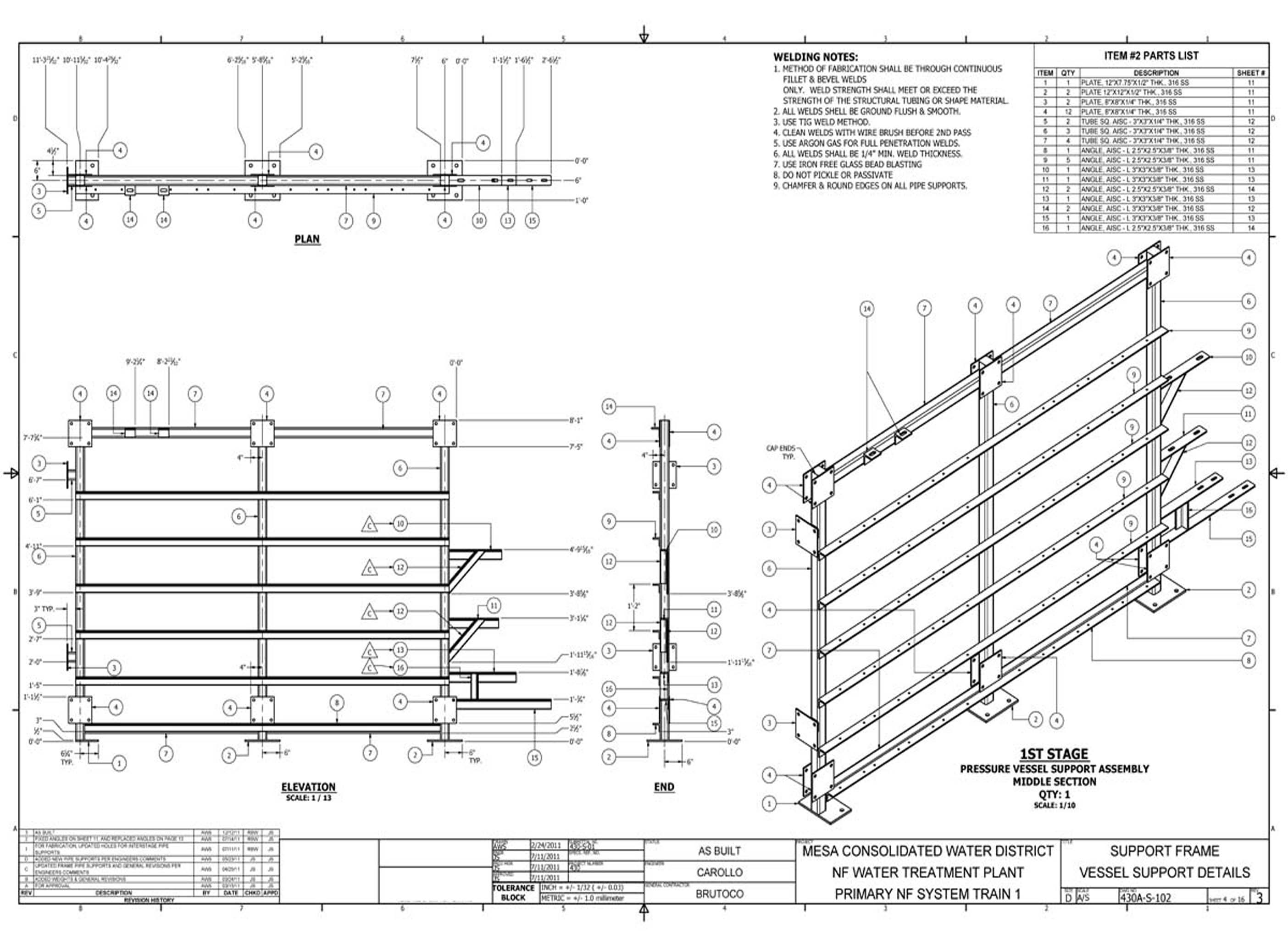
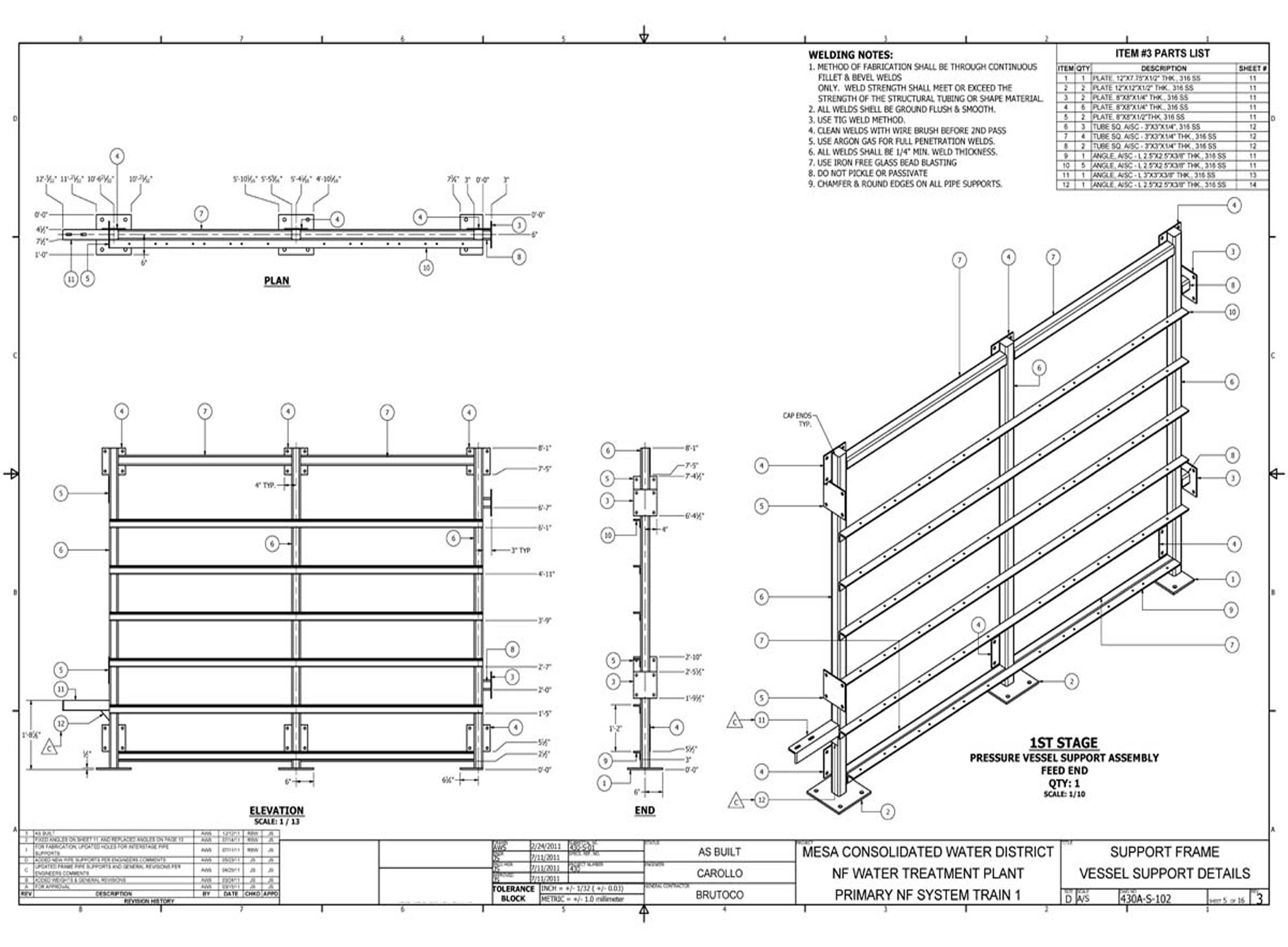
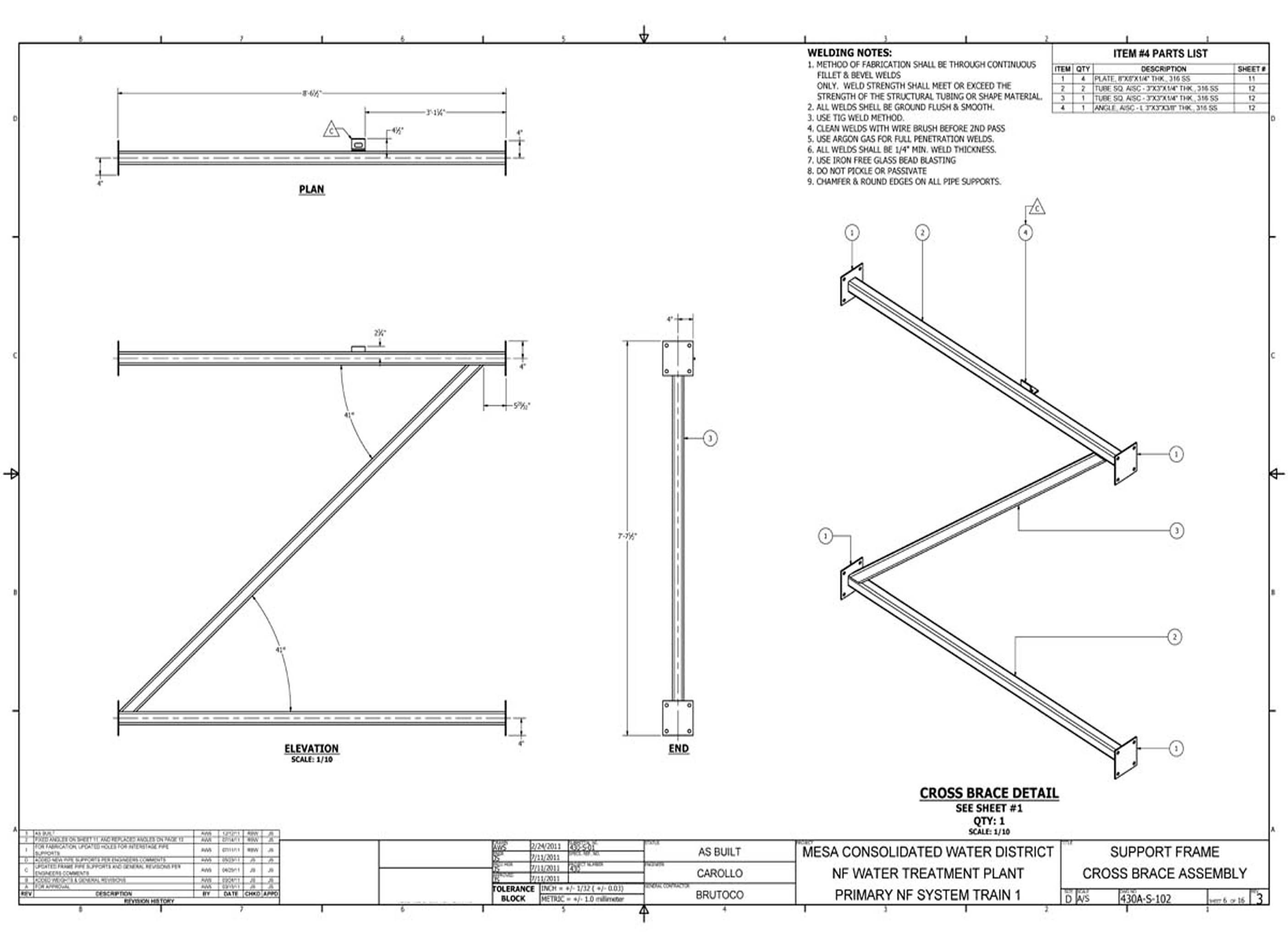
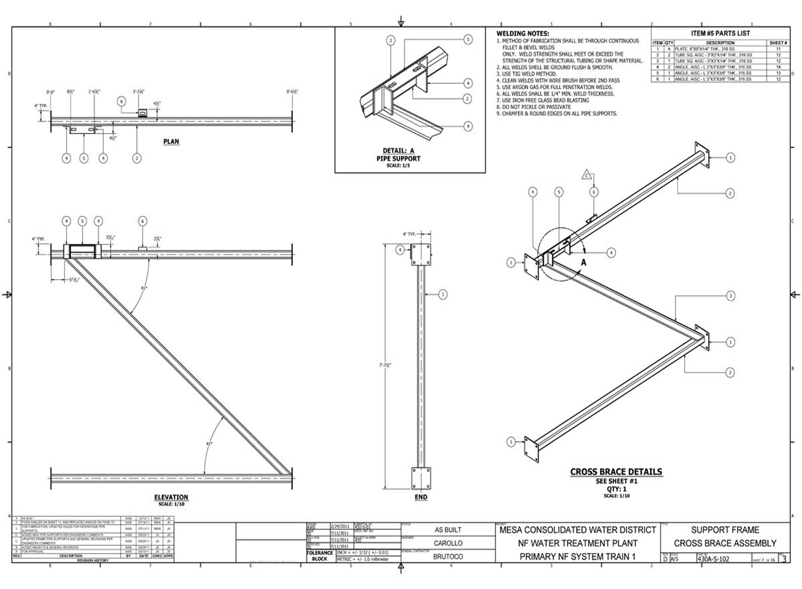
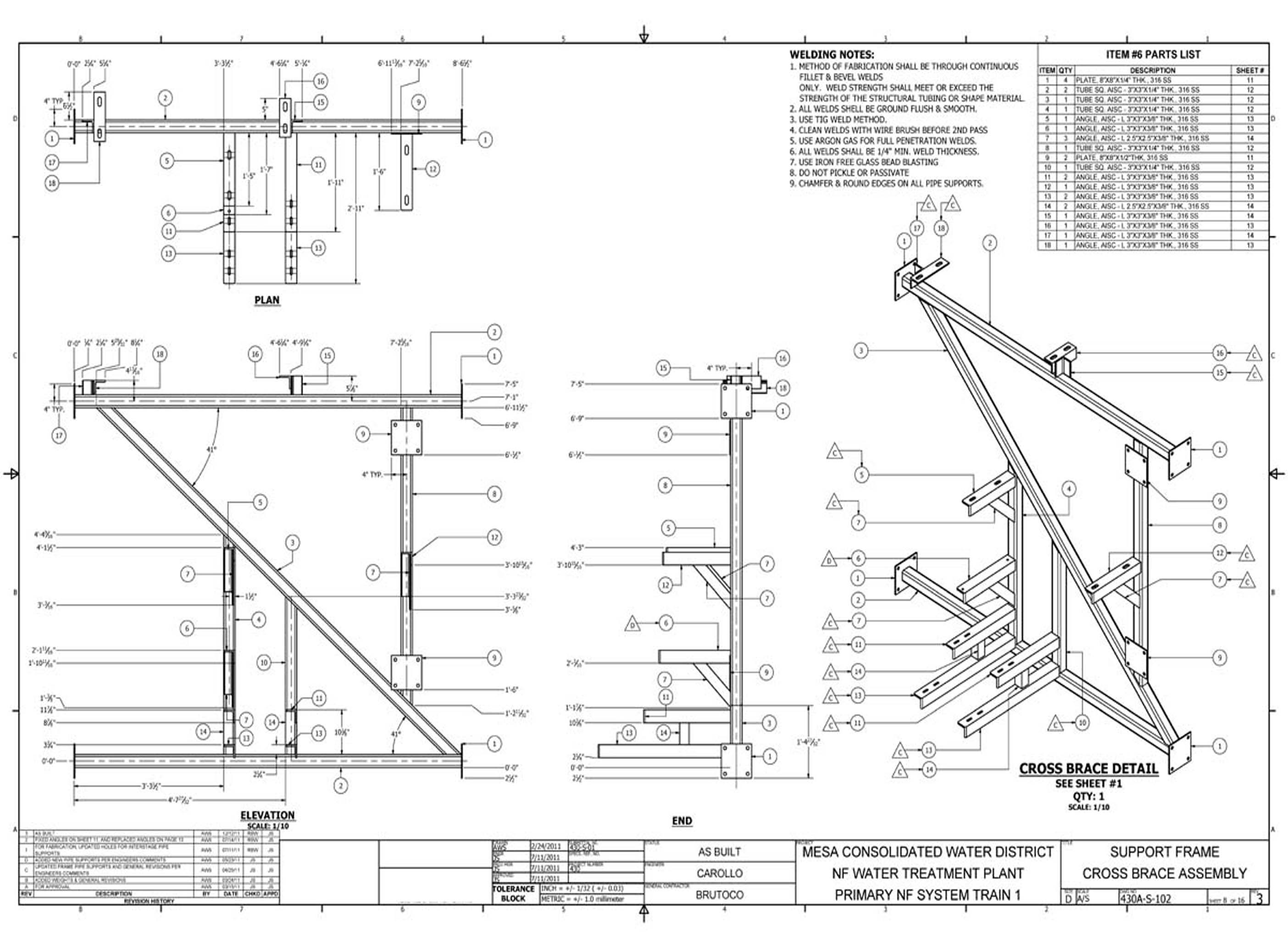
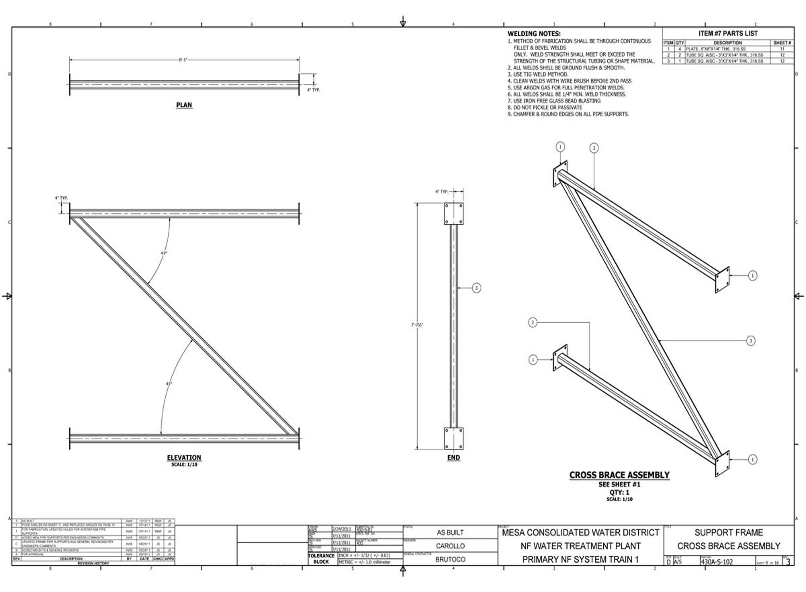
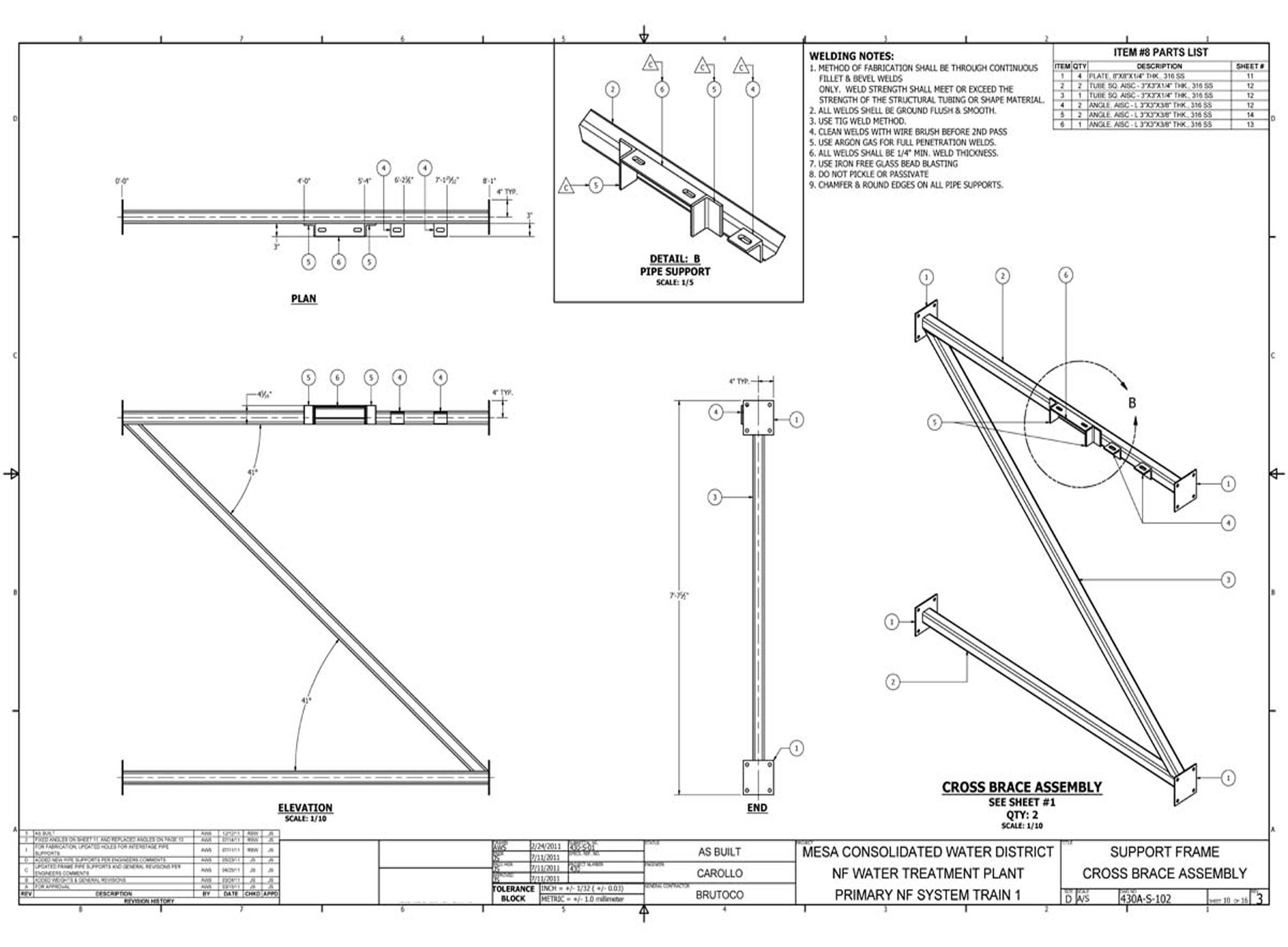
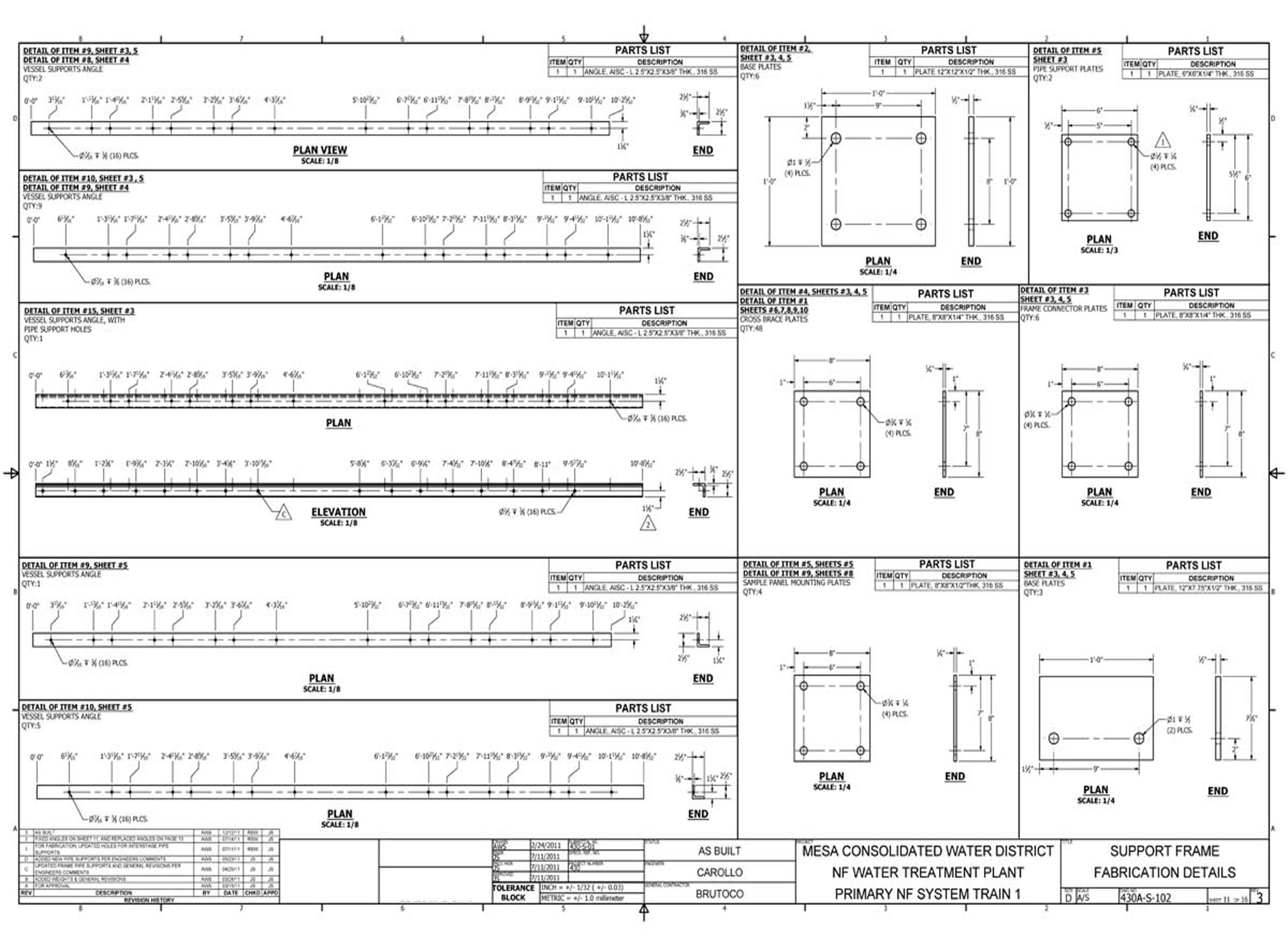
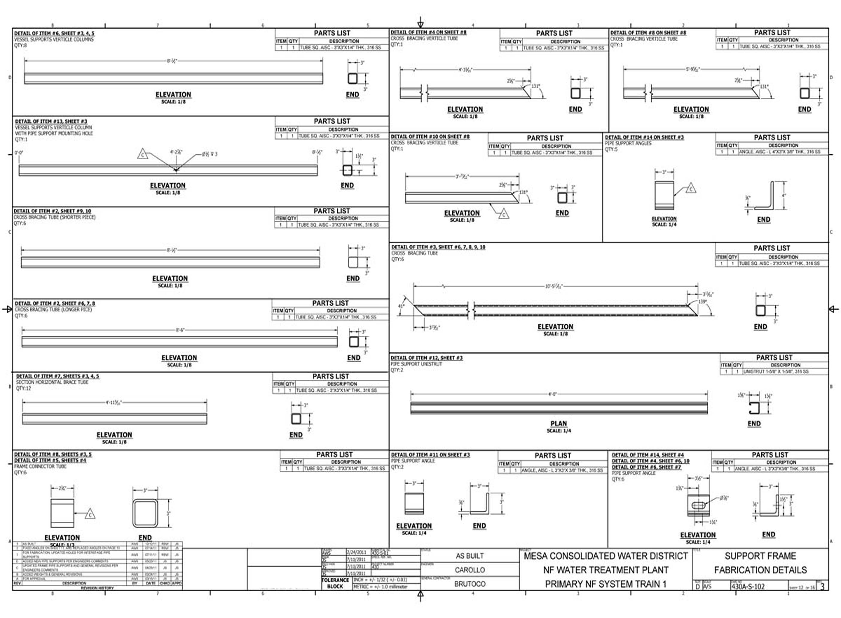
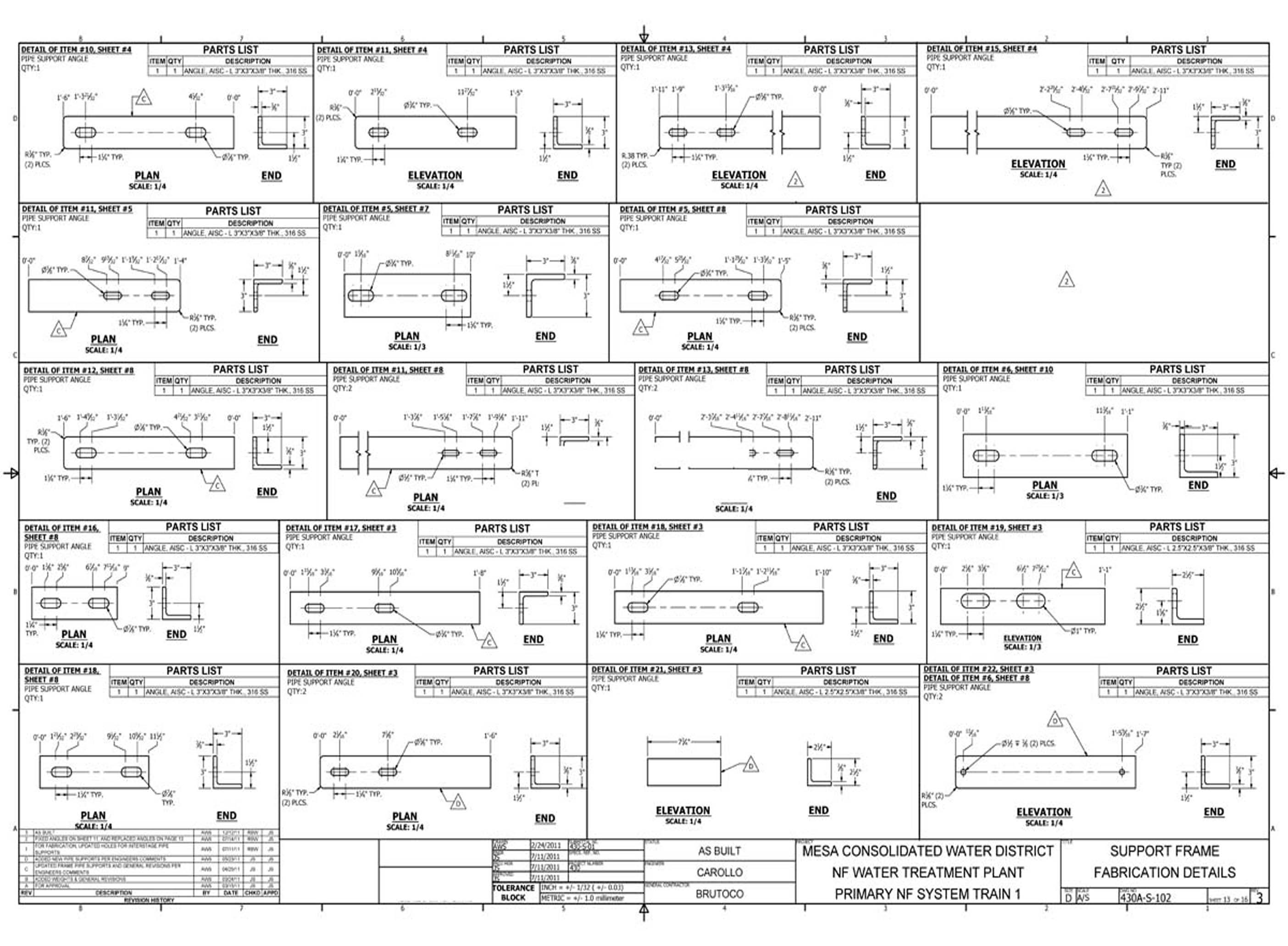
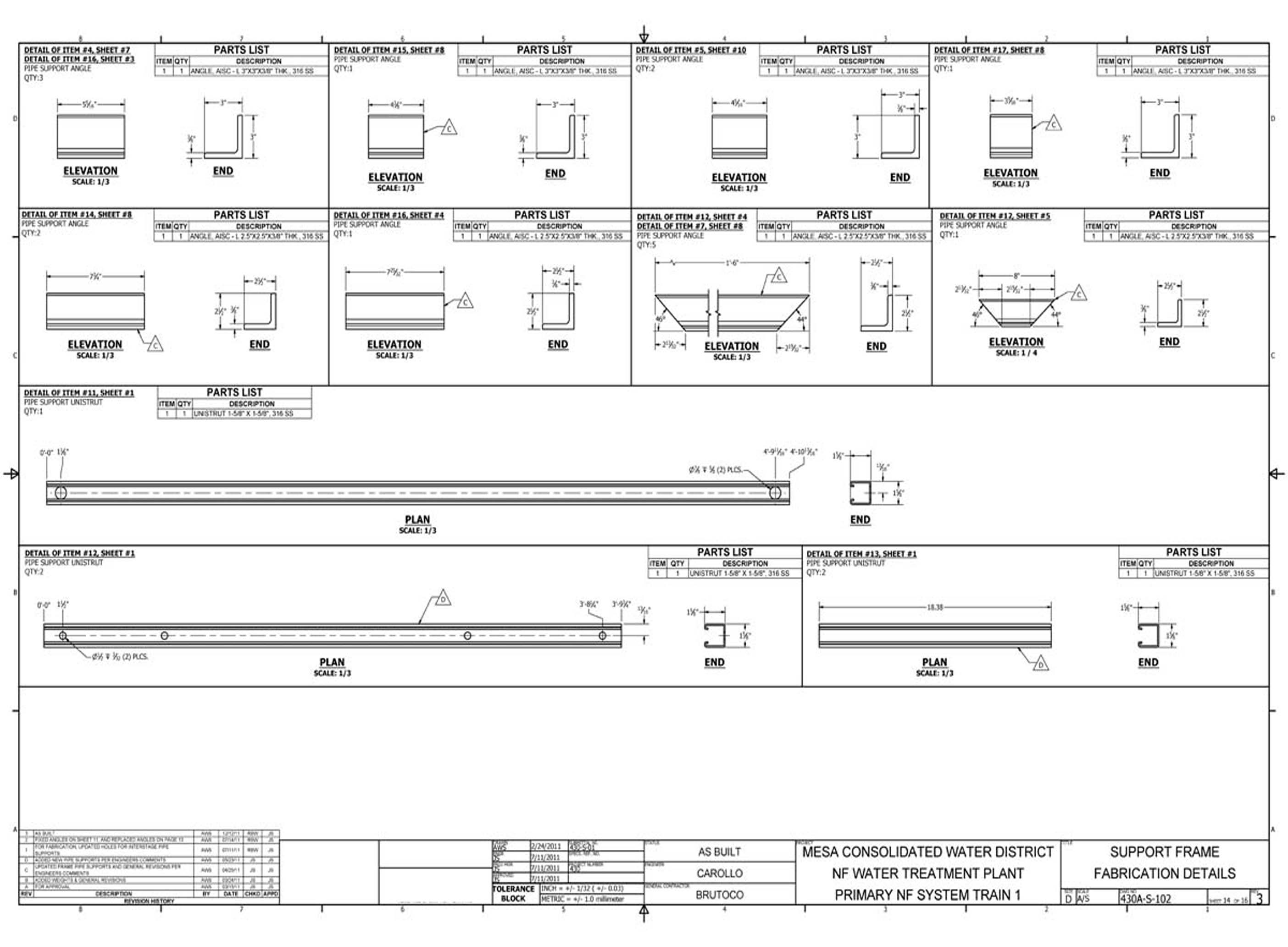
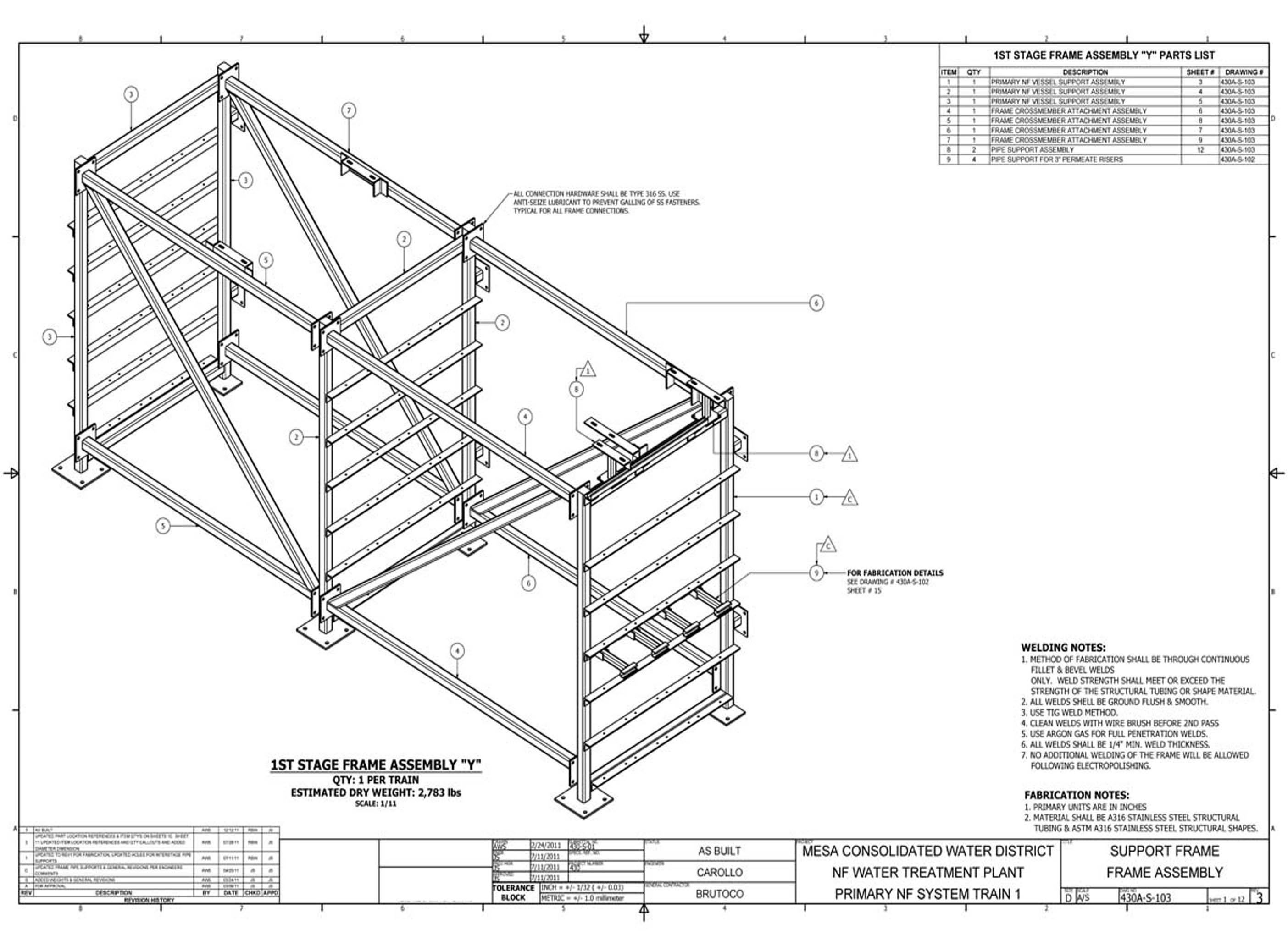
The 1st Stage frame detail drawings document the structural framing assemblies specific to the first RO stage at Costa Mesa. These 22 sheets provide the dimensional and connection references required for fabrication and installation of the 1st stage support structure.
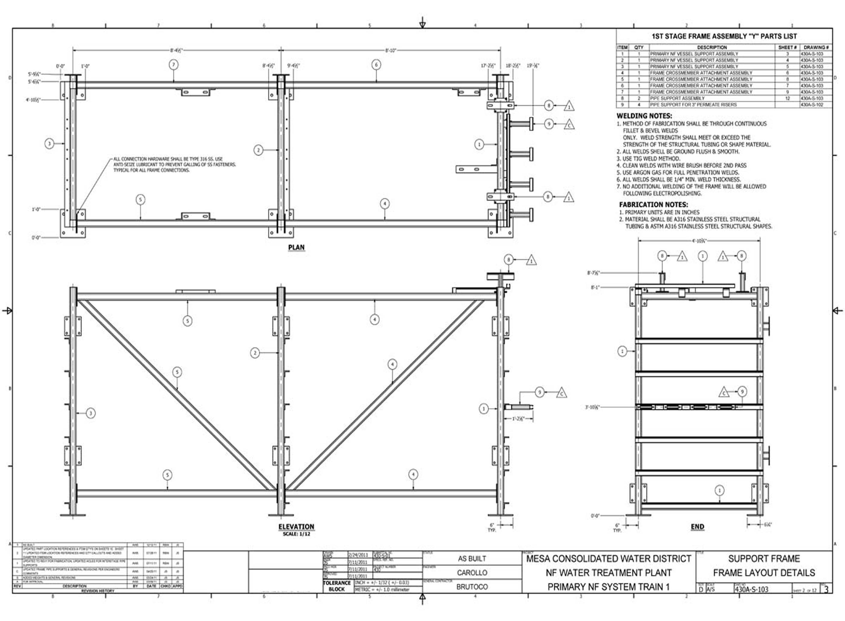
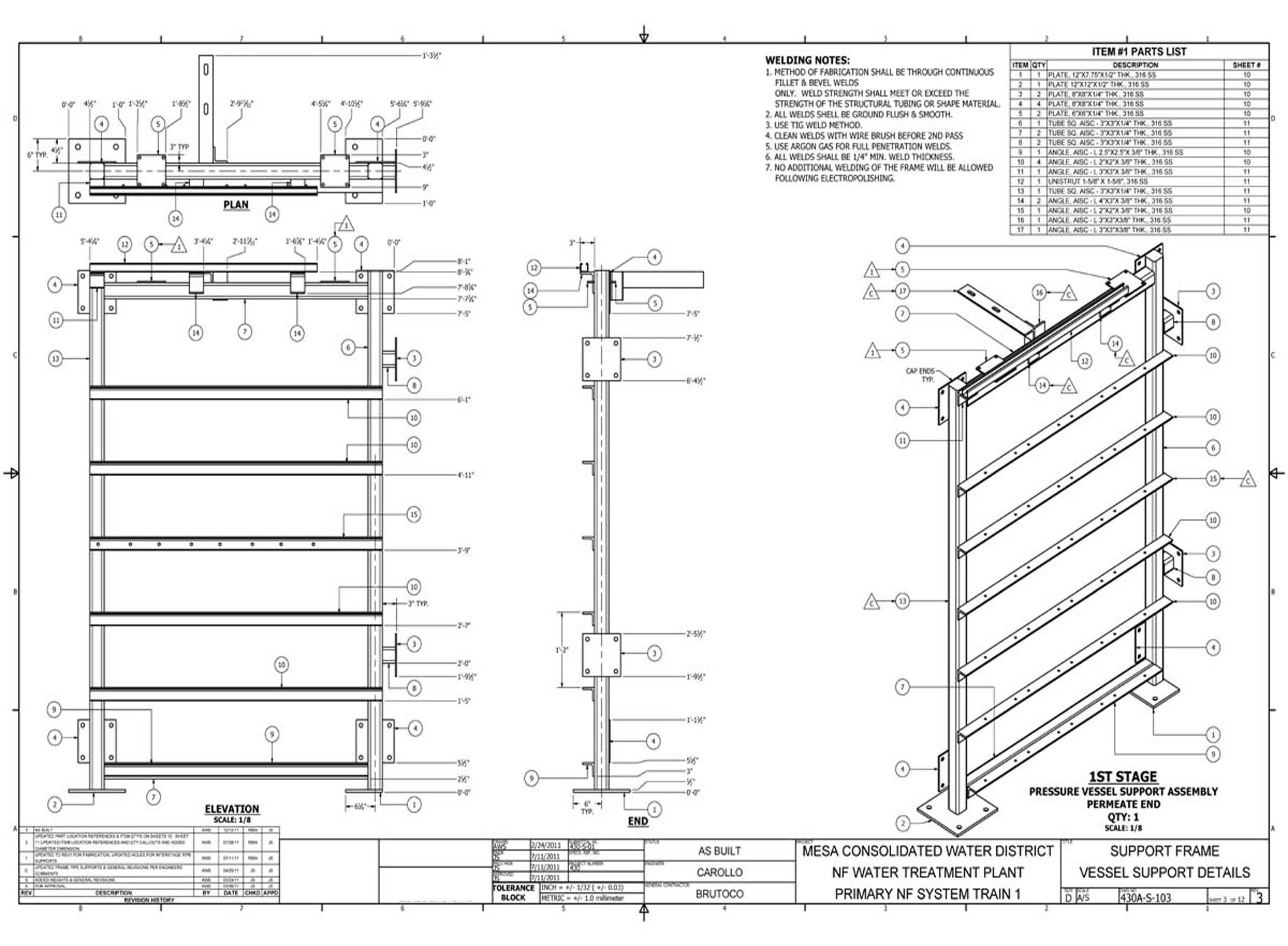
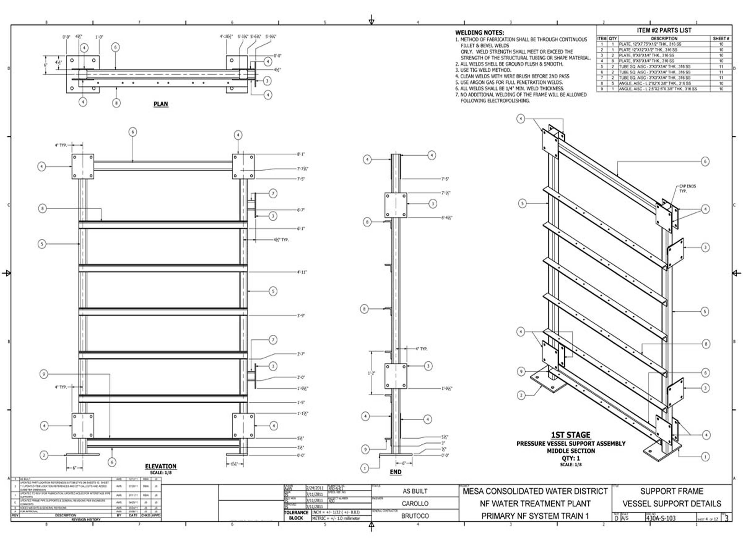
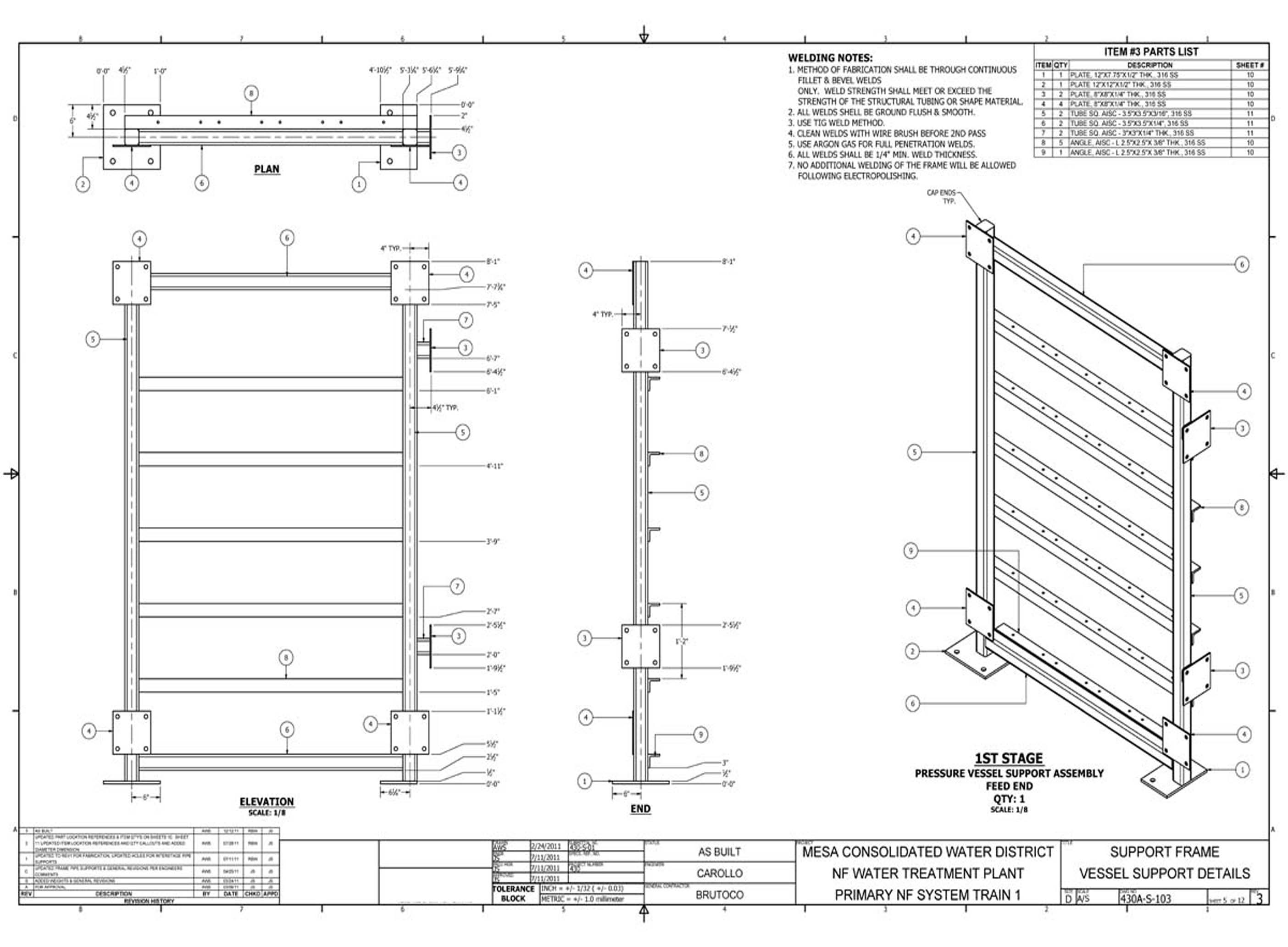
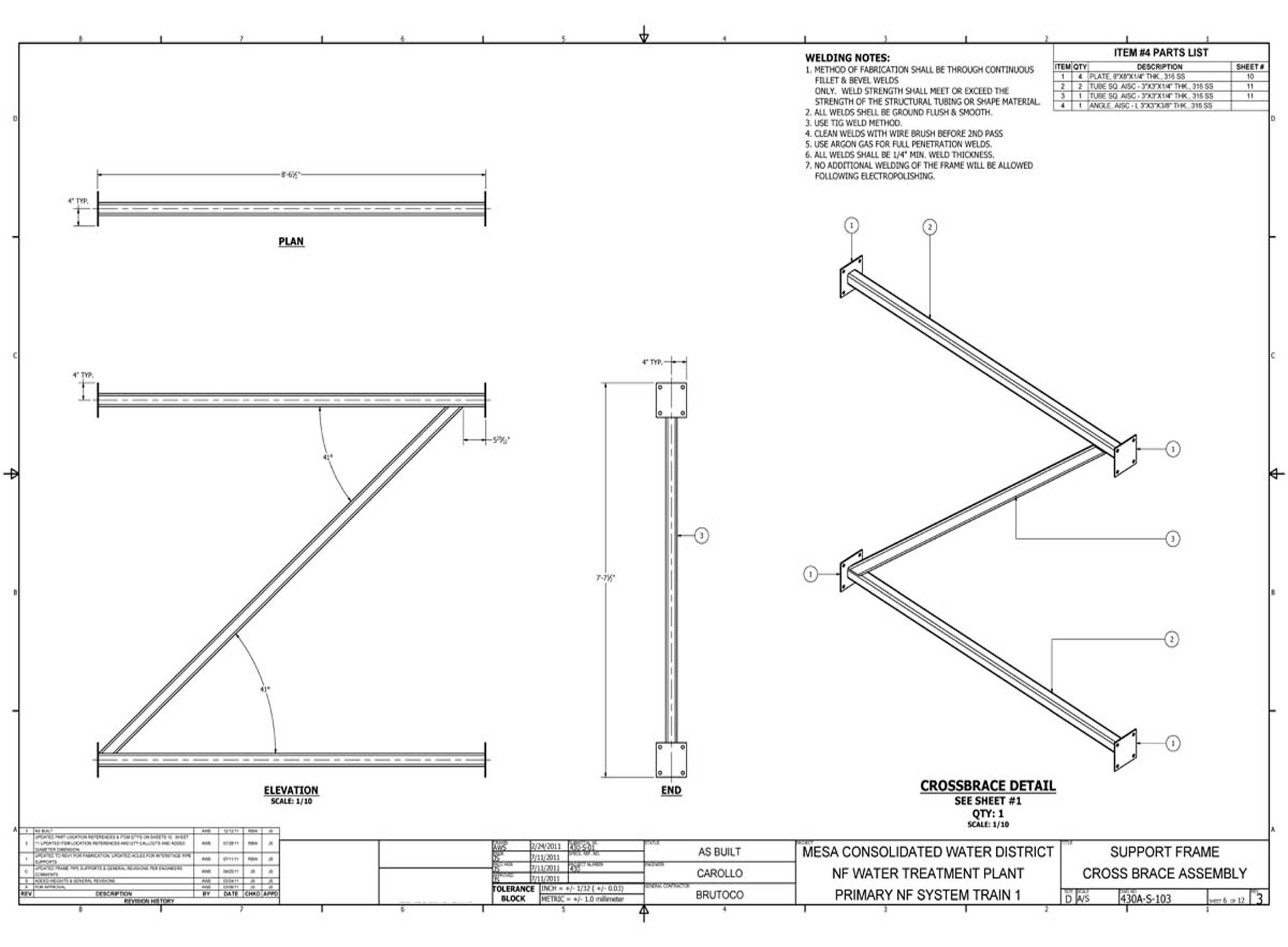
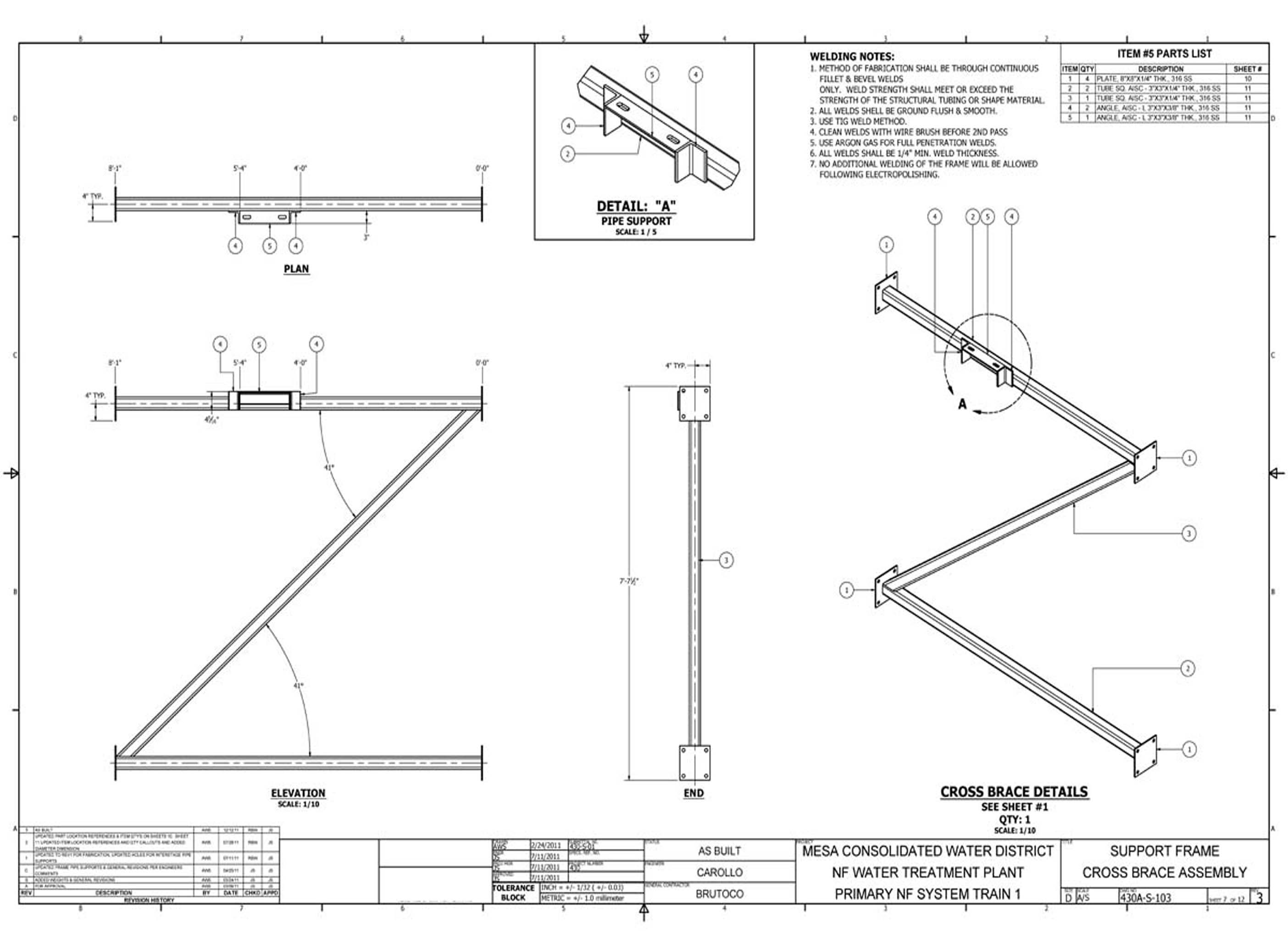
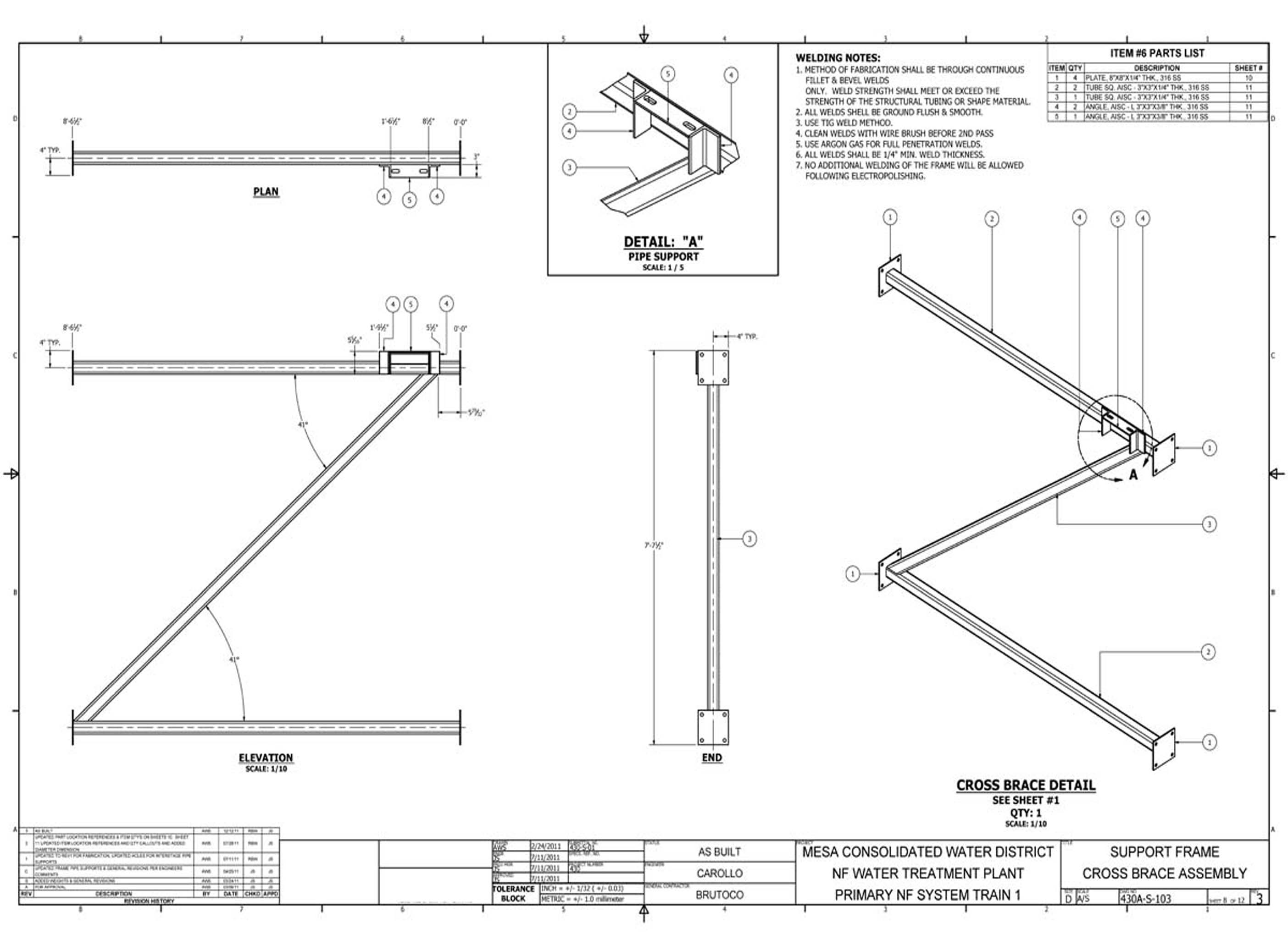
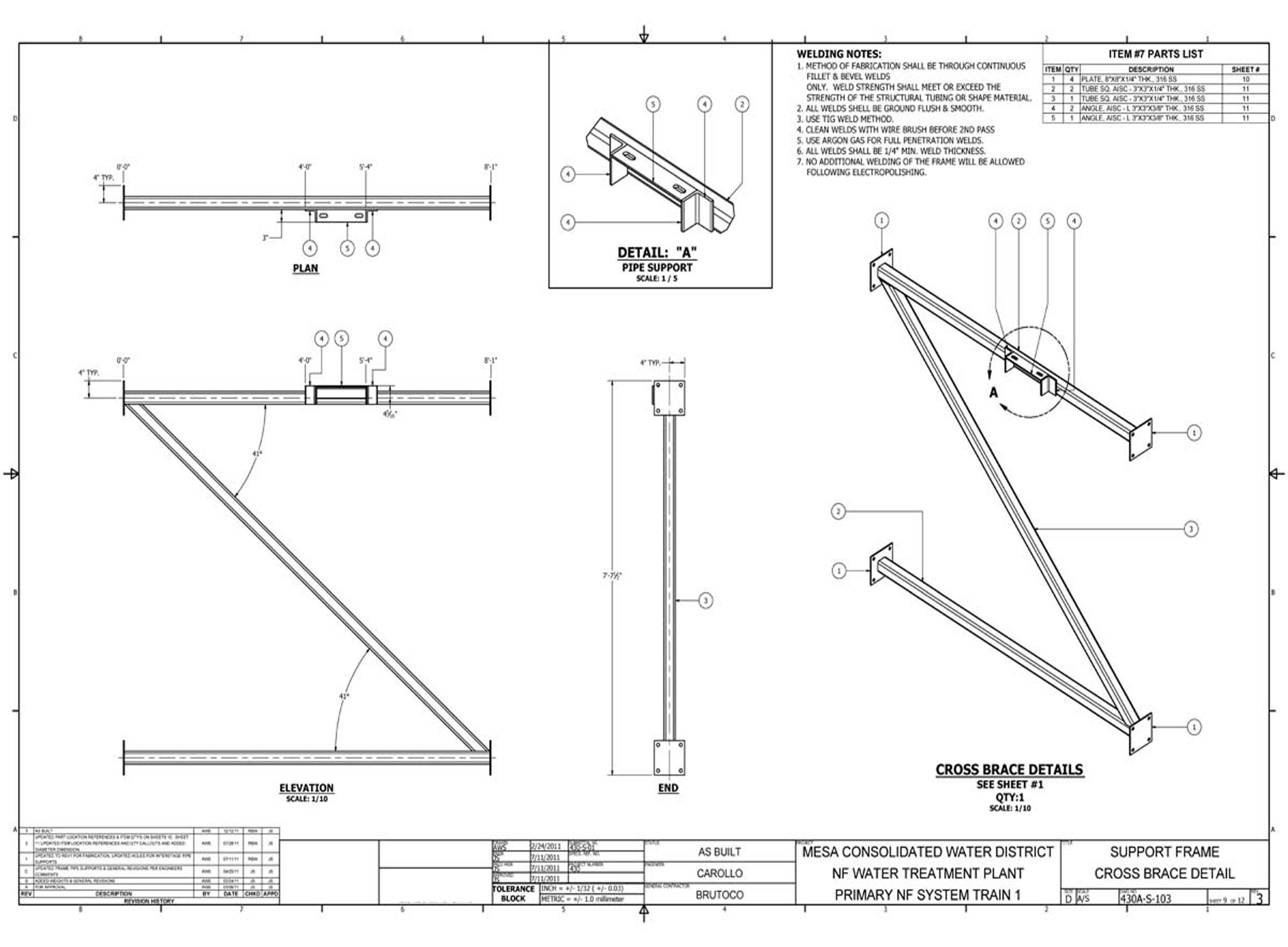
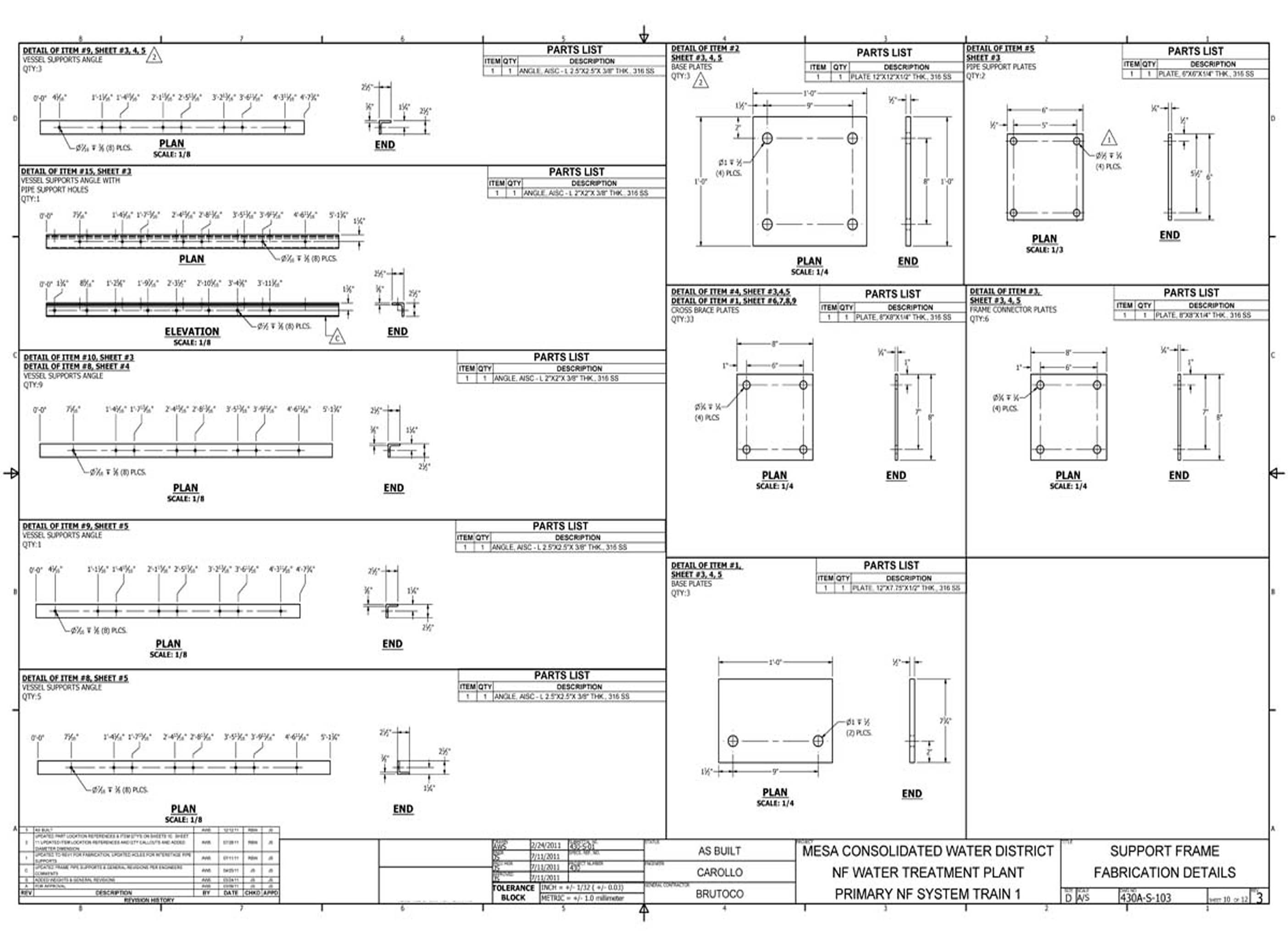
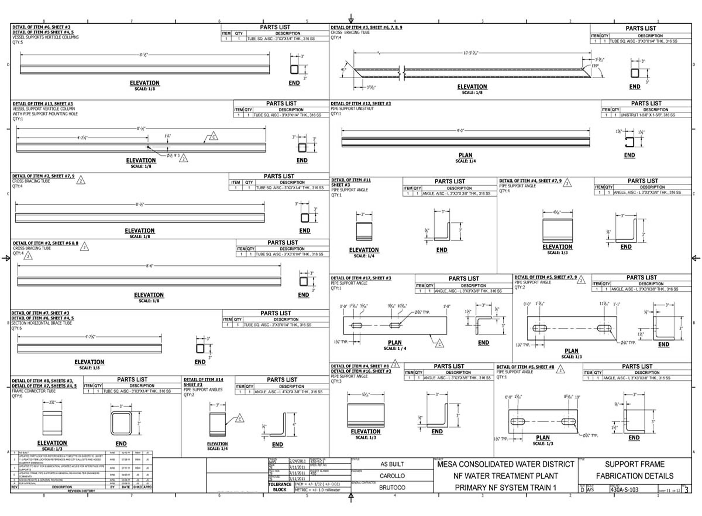
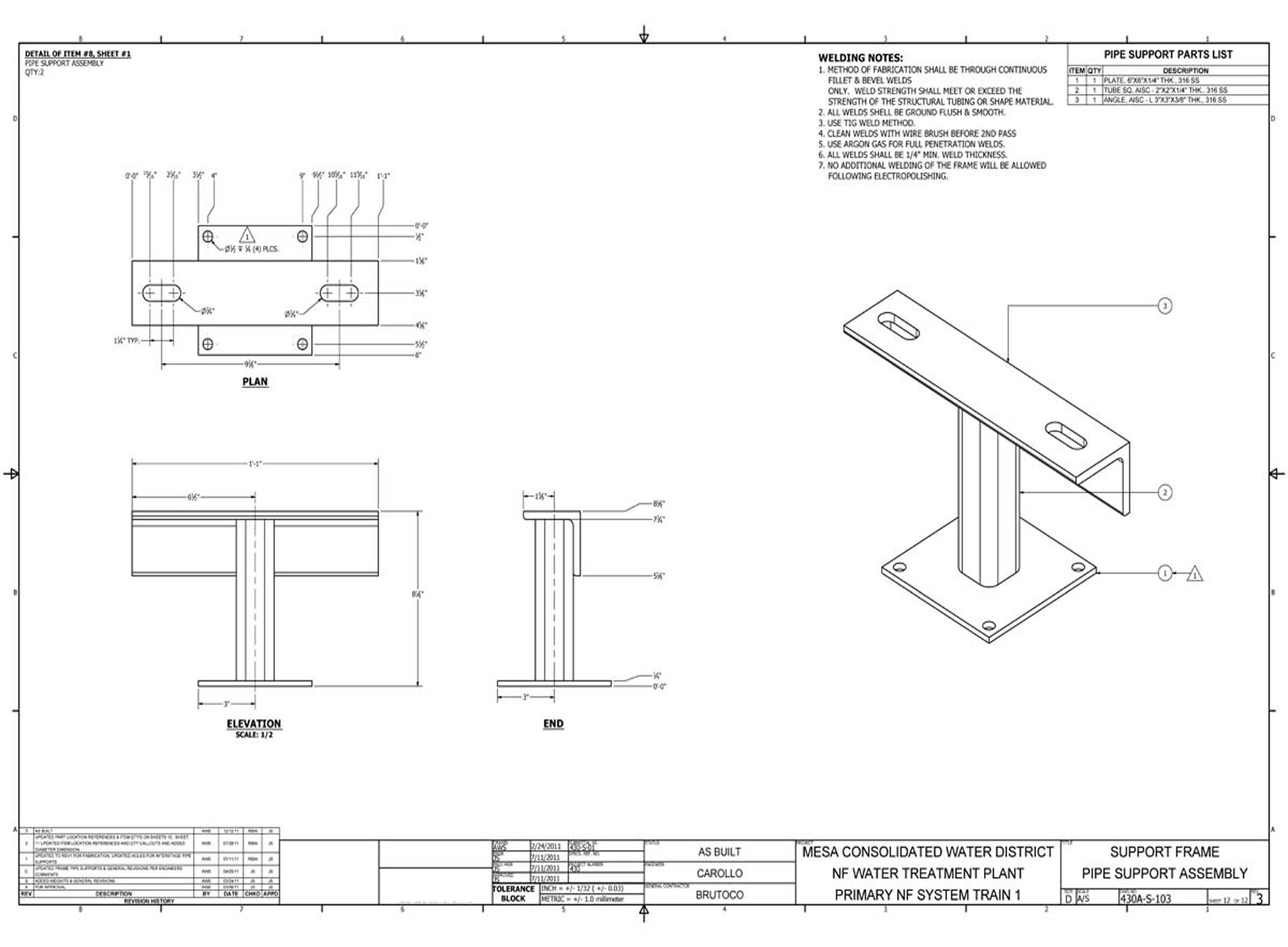
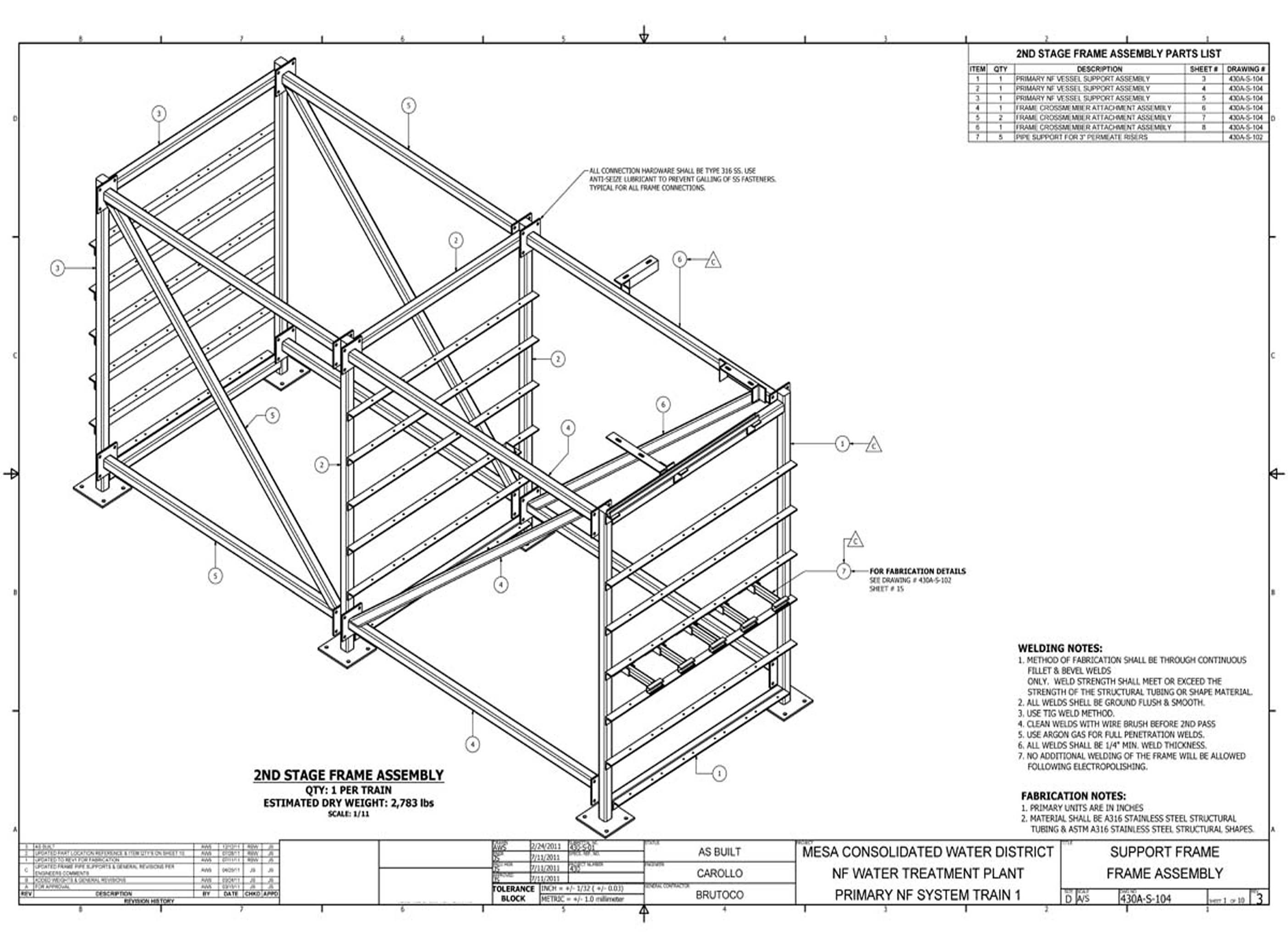
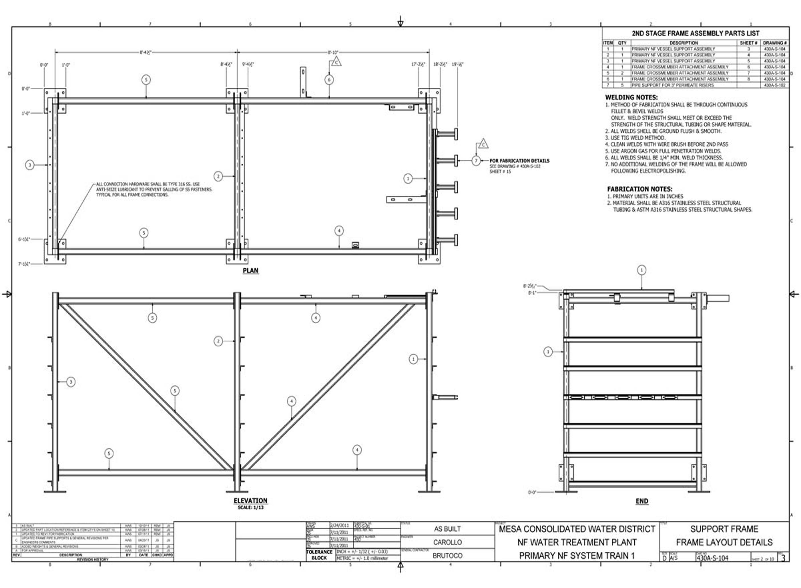
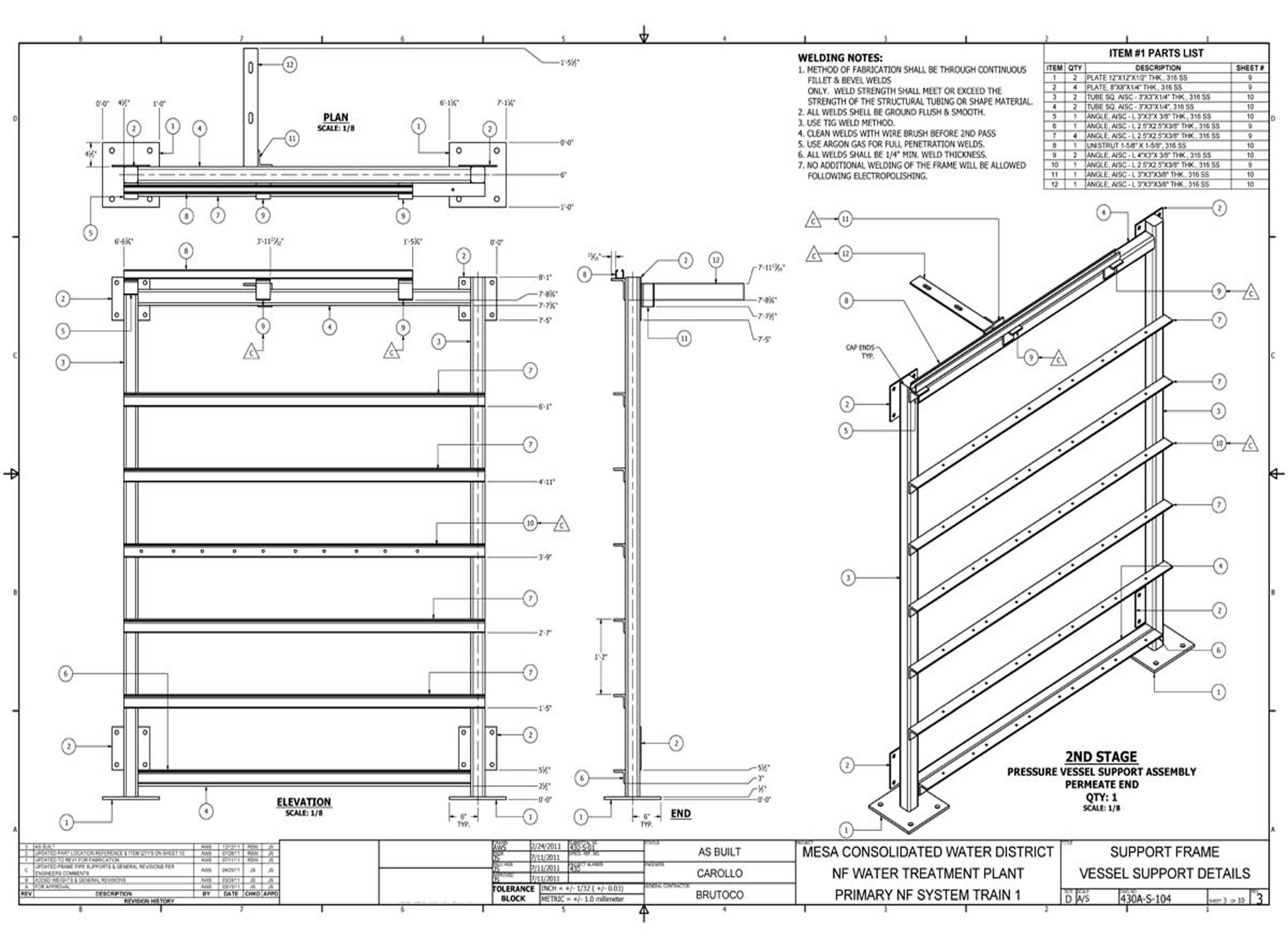
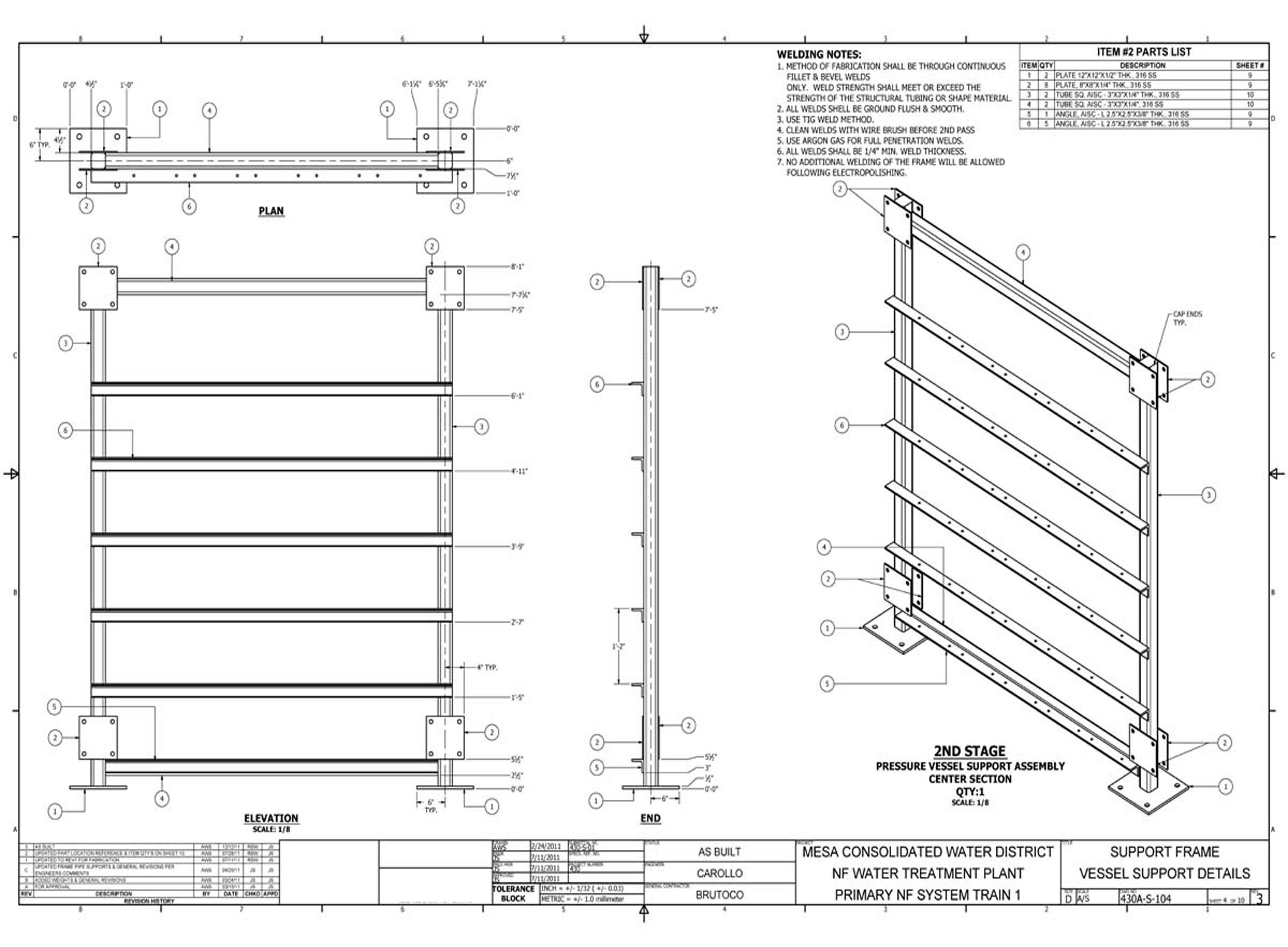
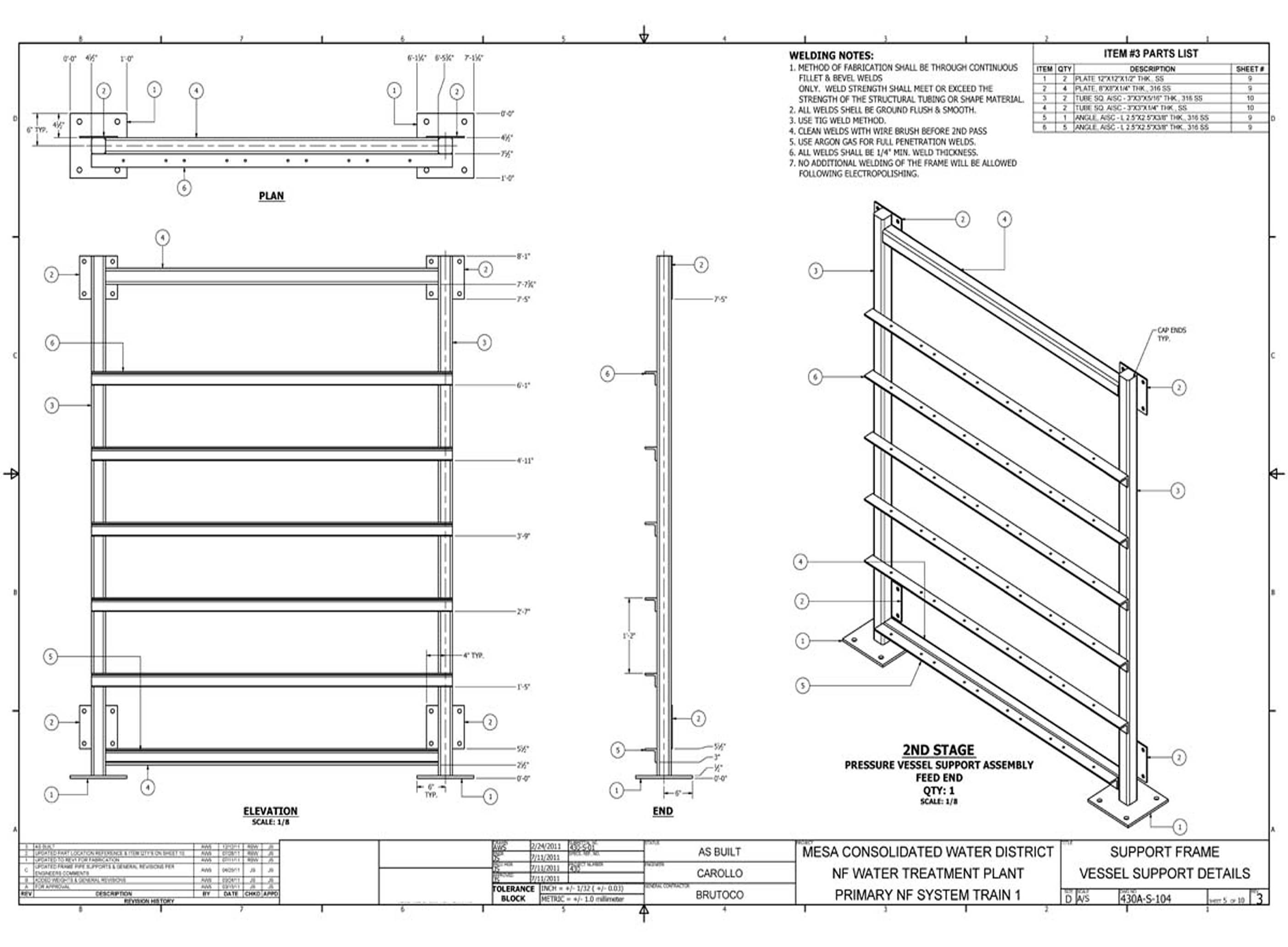
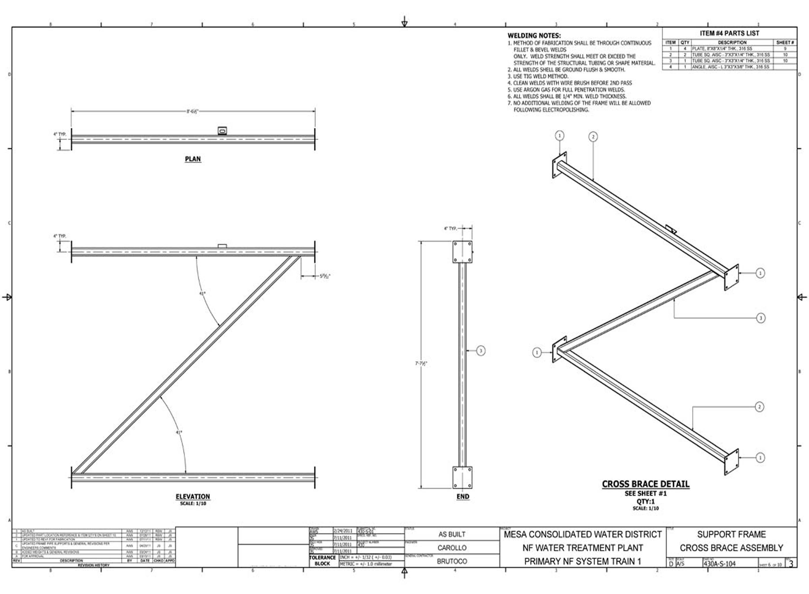
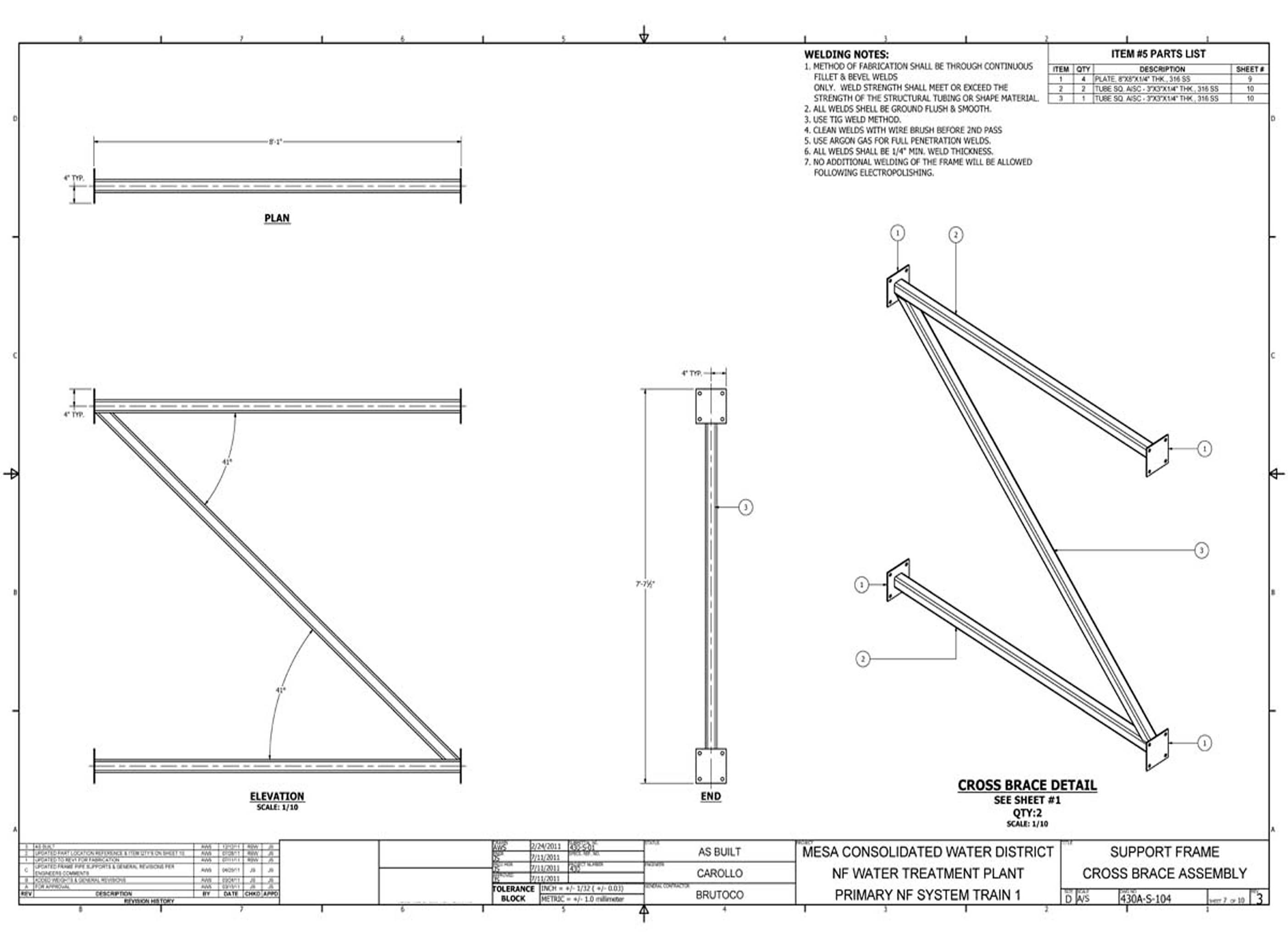
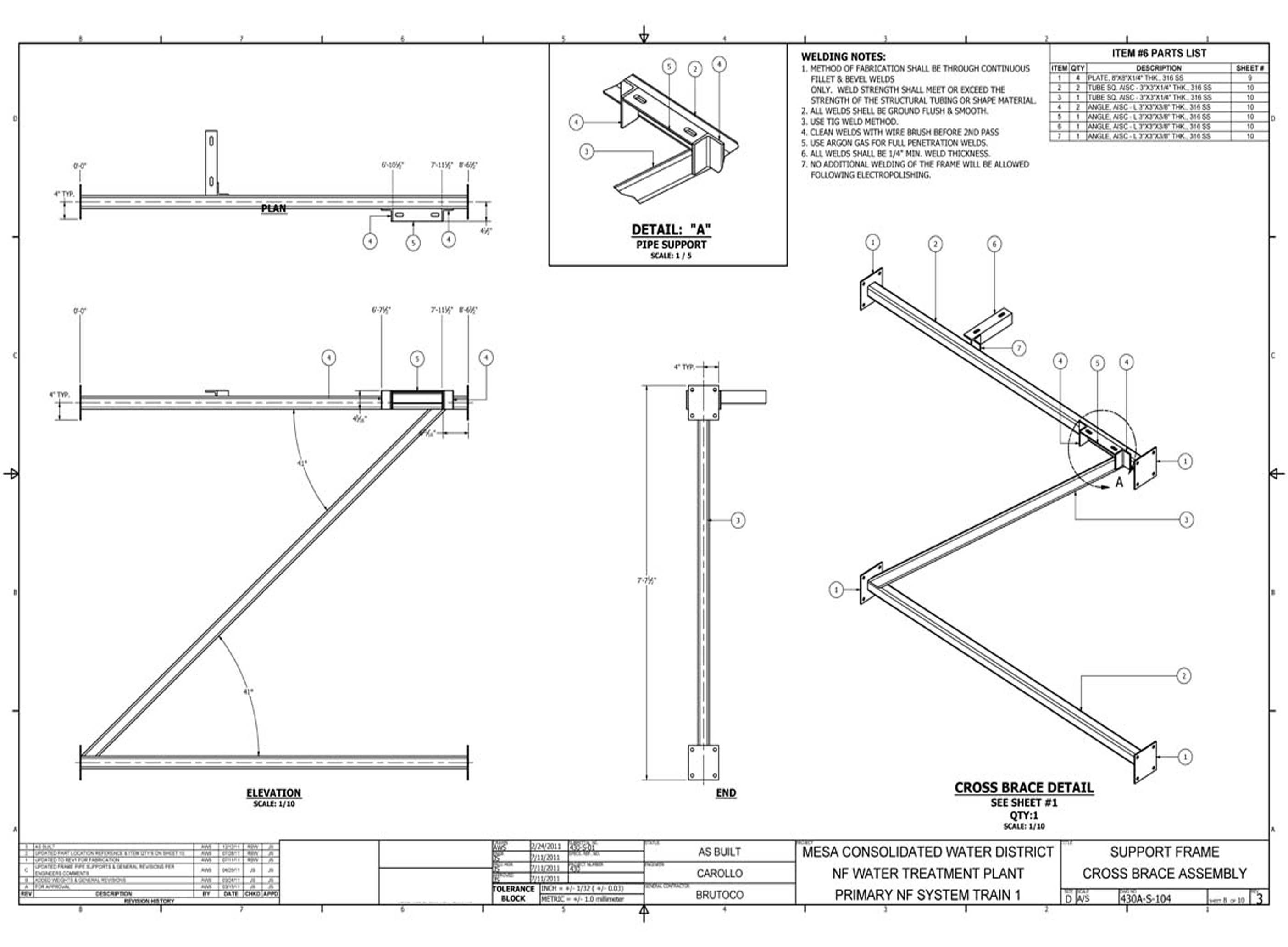
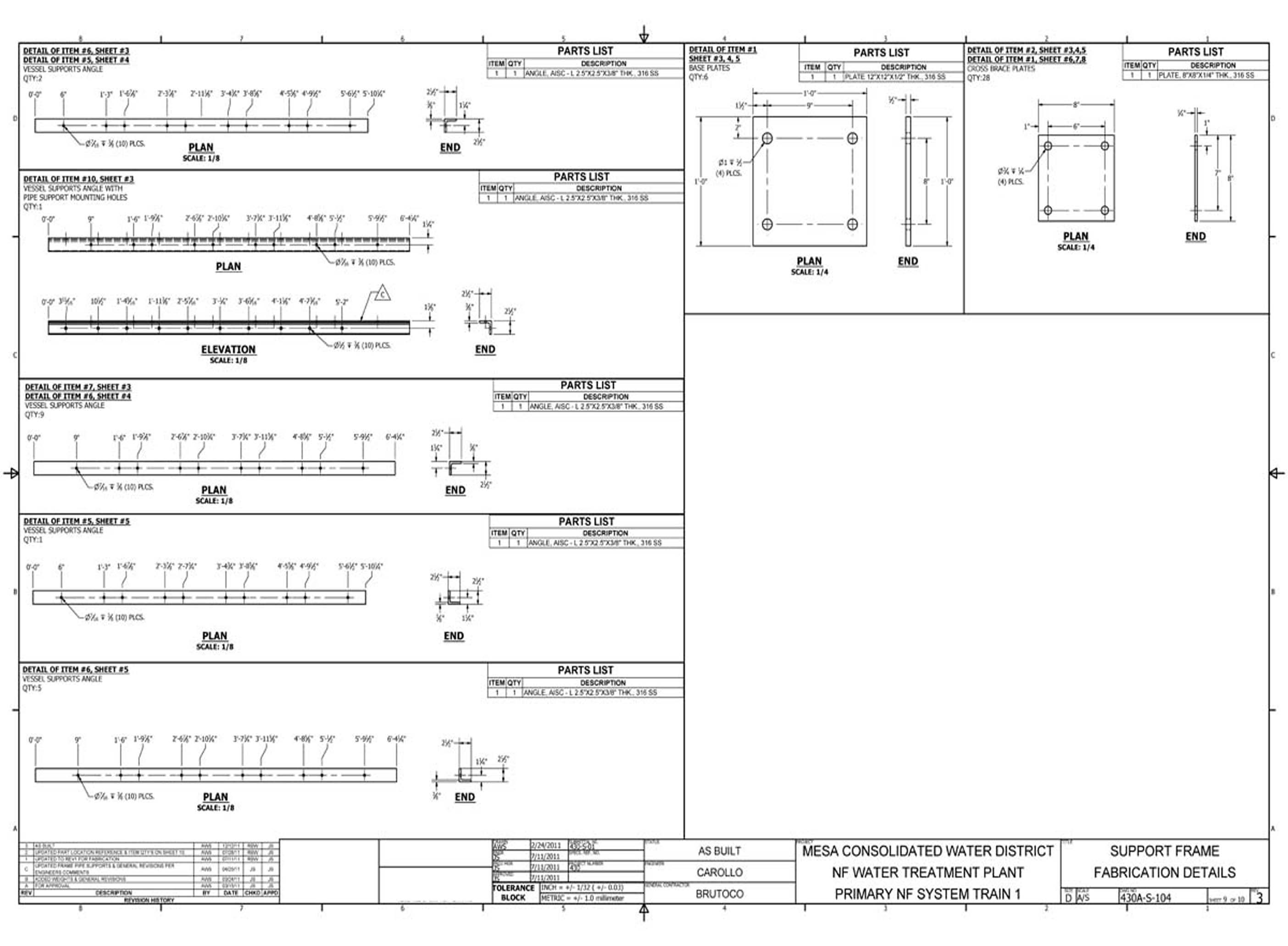
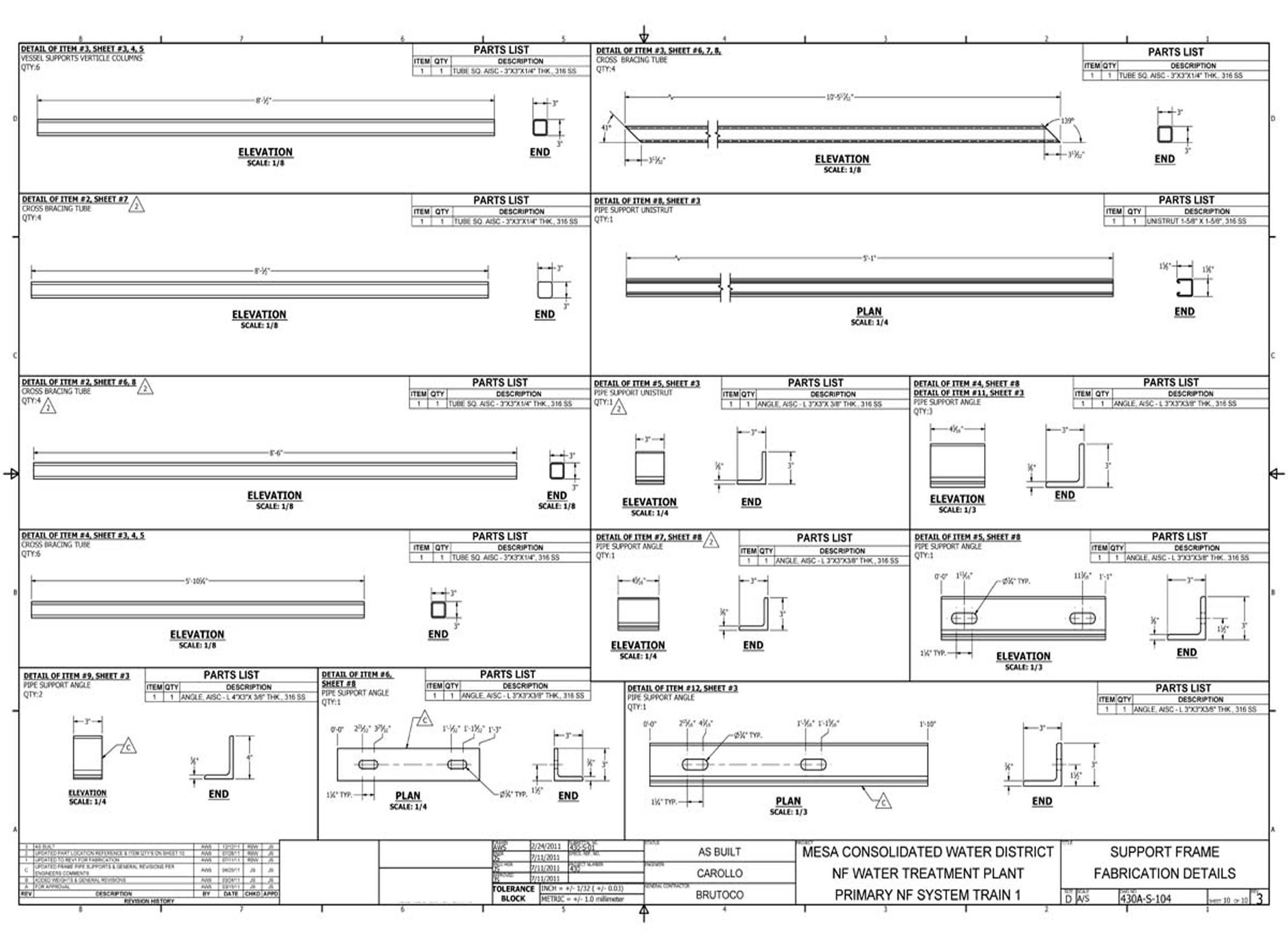
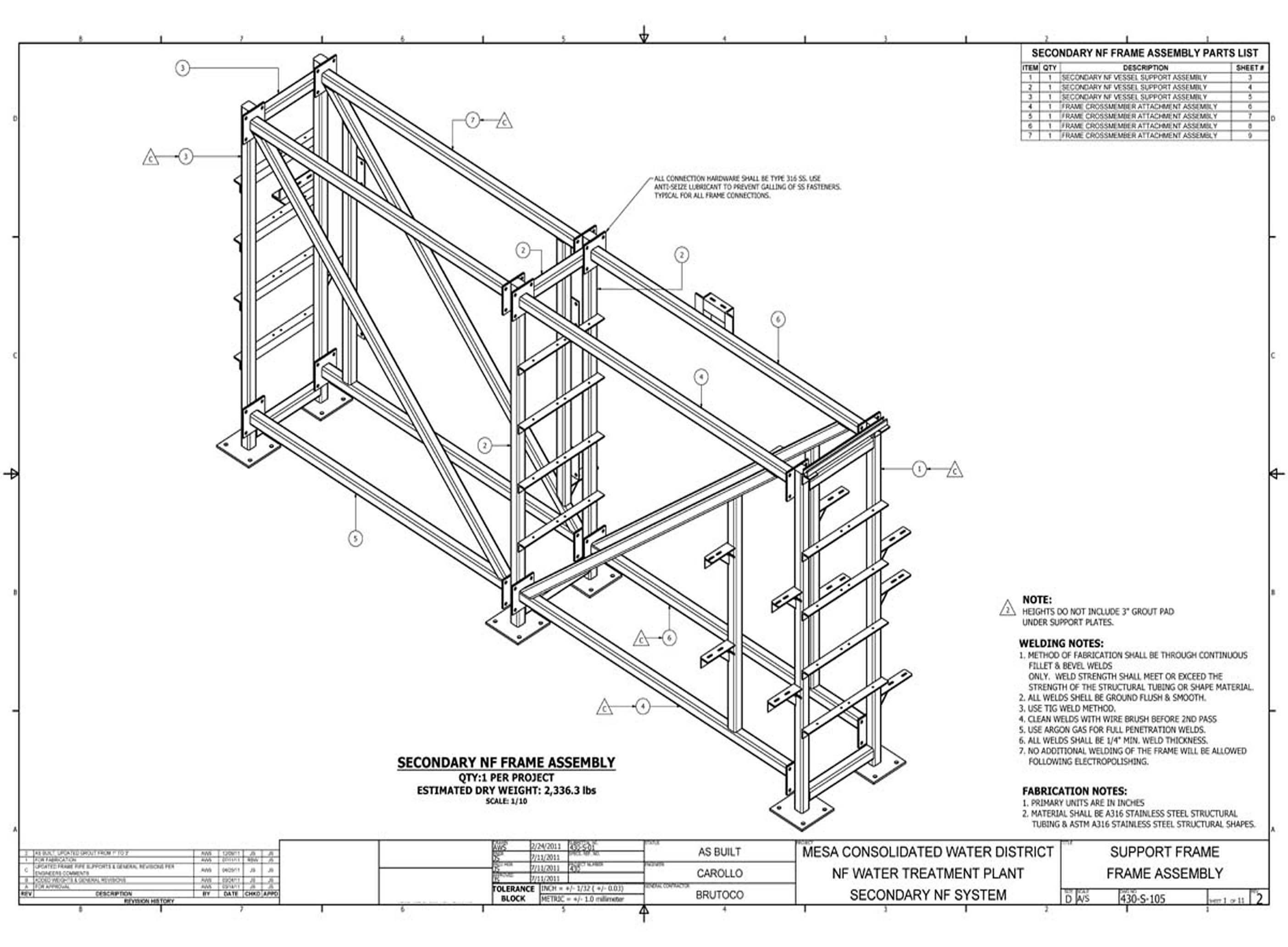
The 2nd Stage frame detail drawings document the structural framing assemblies for the second RO stage at Costa Mesa. These 11 sheets define the connection details, weld specifications, and dimensional data required for fabrication and assembly of the 2nd stage support structure.
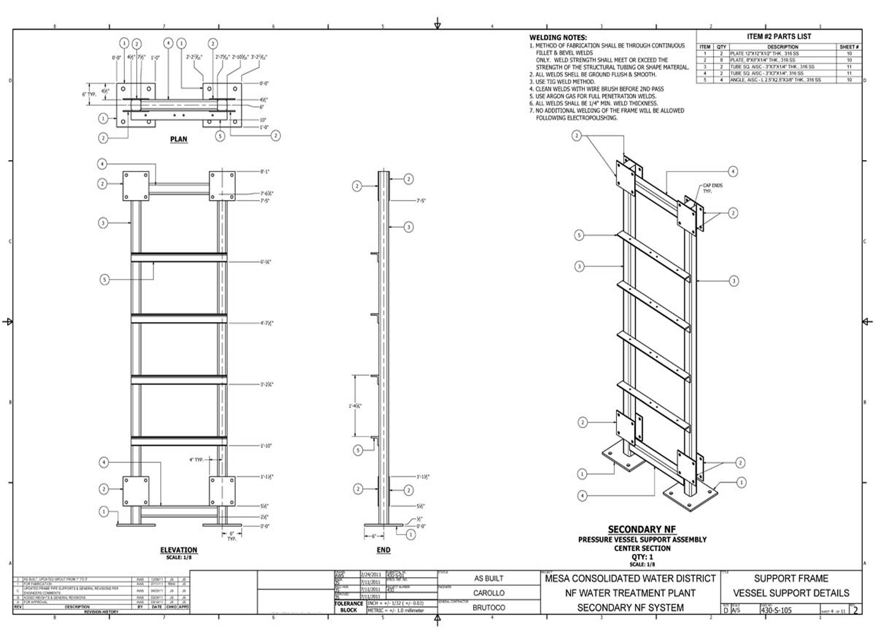
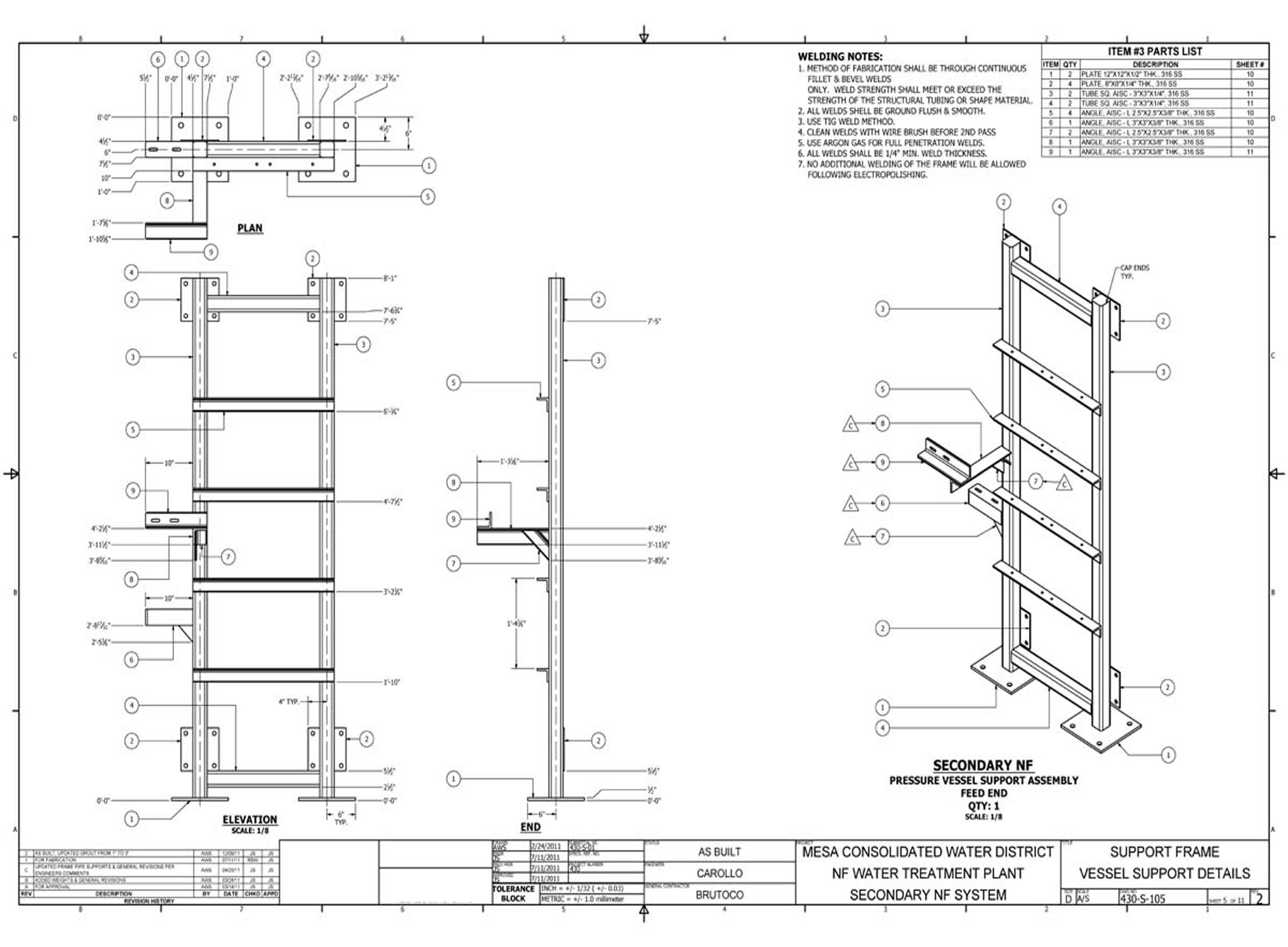
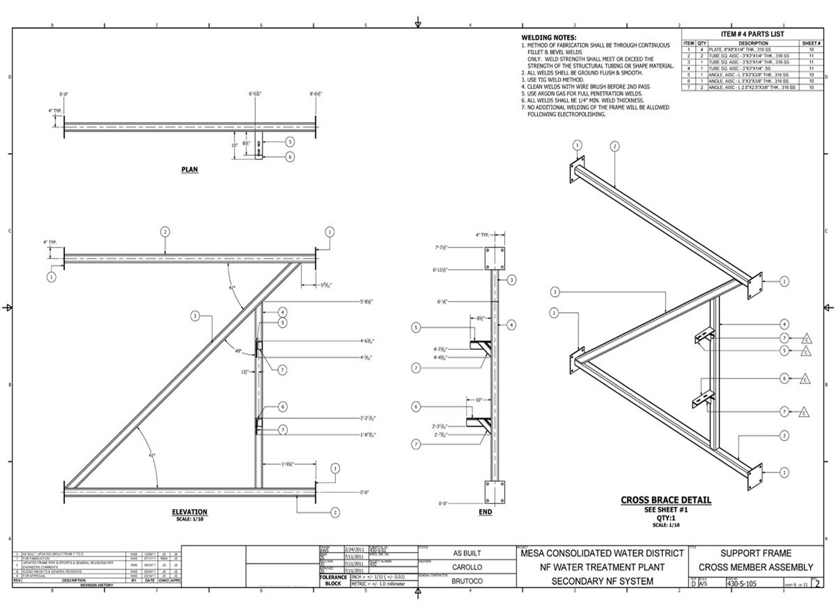
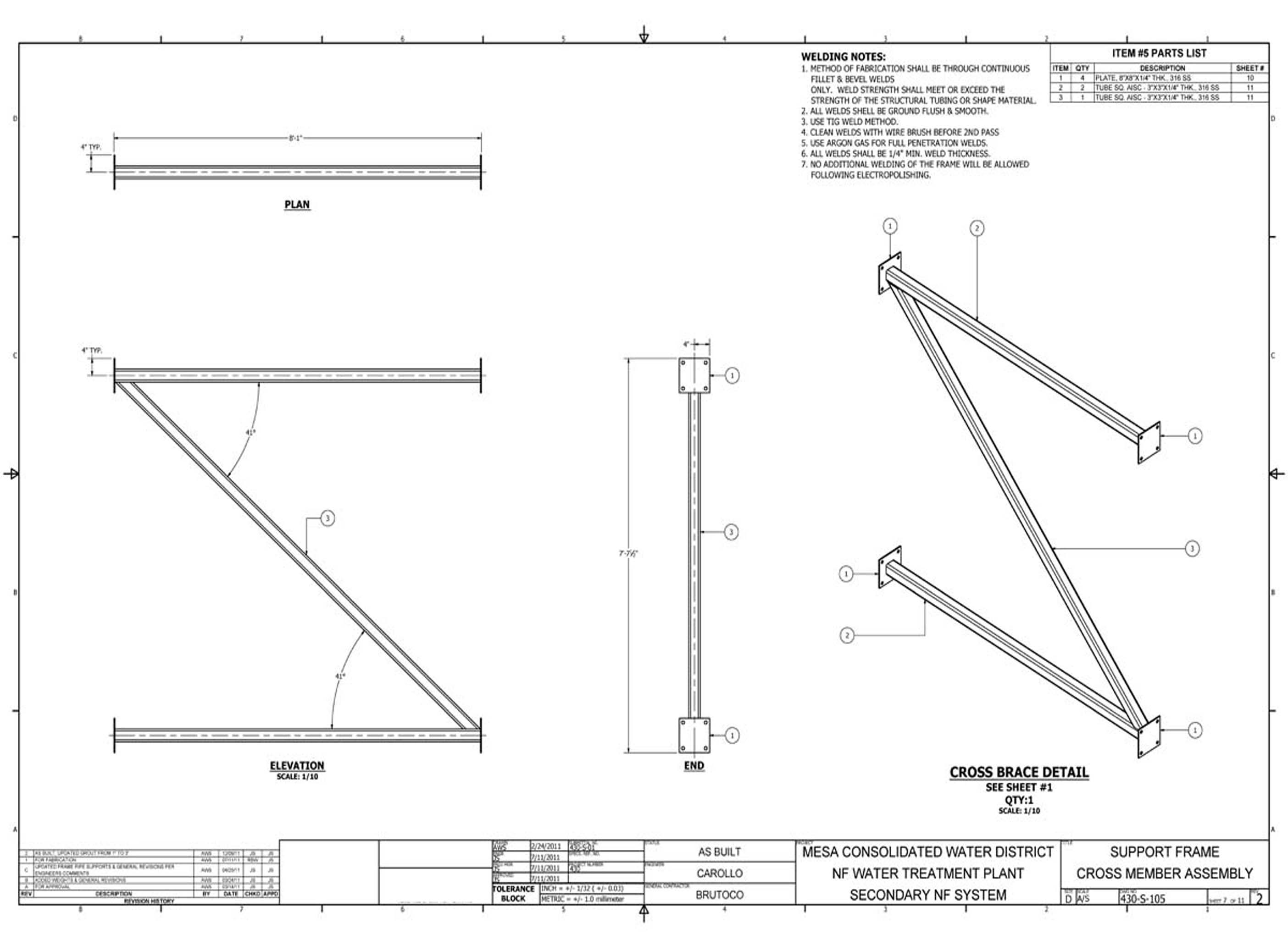
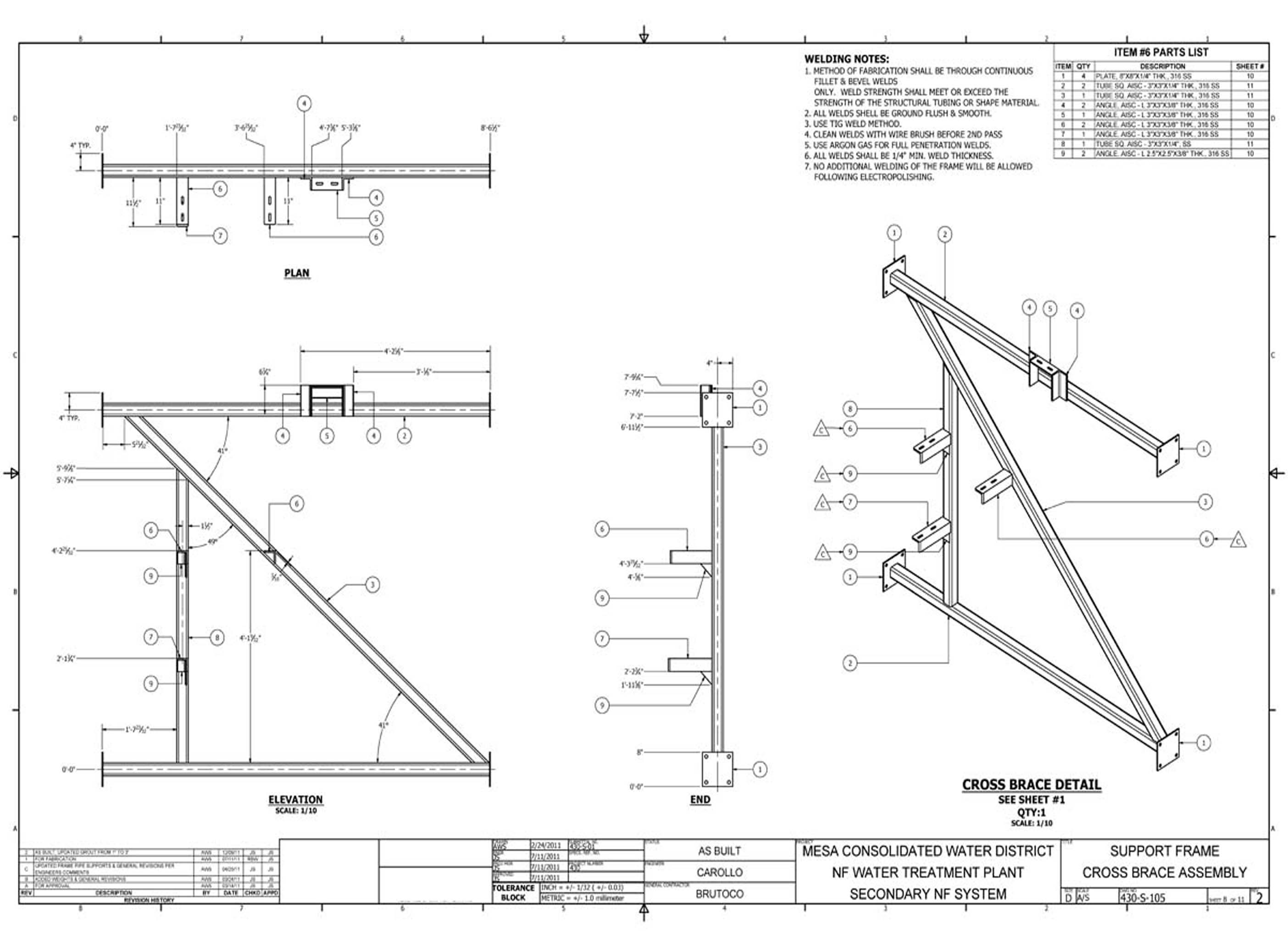
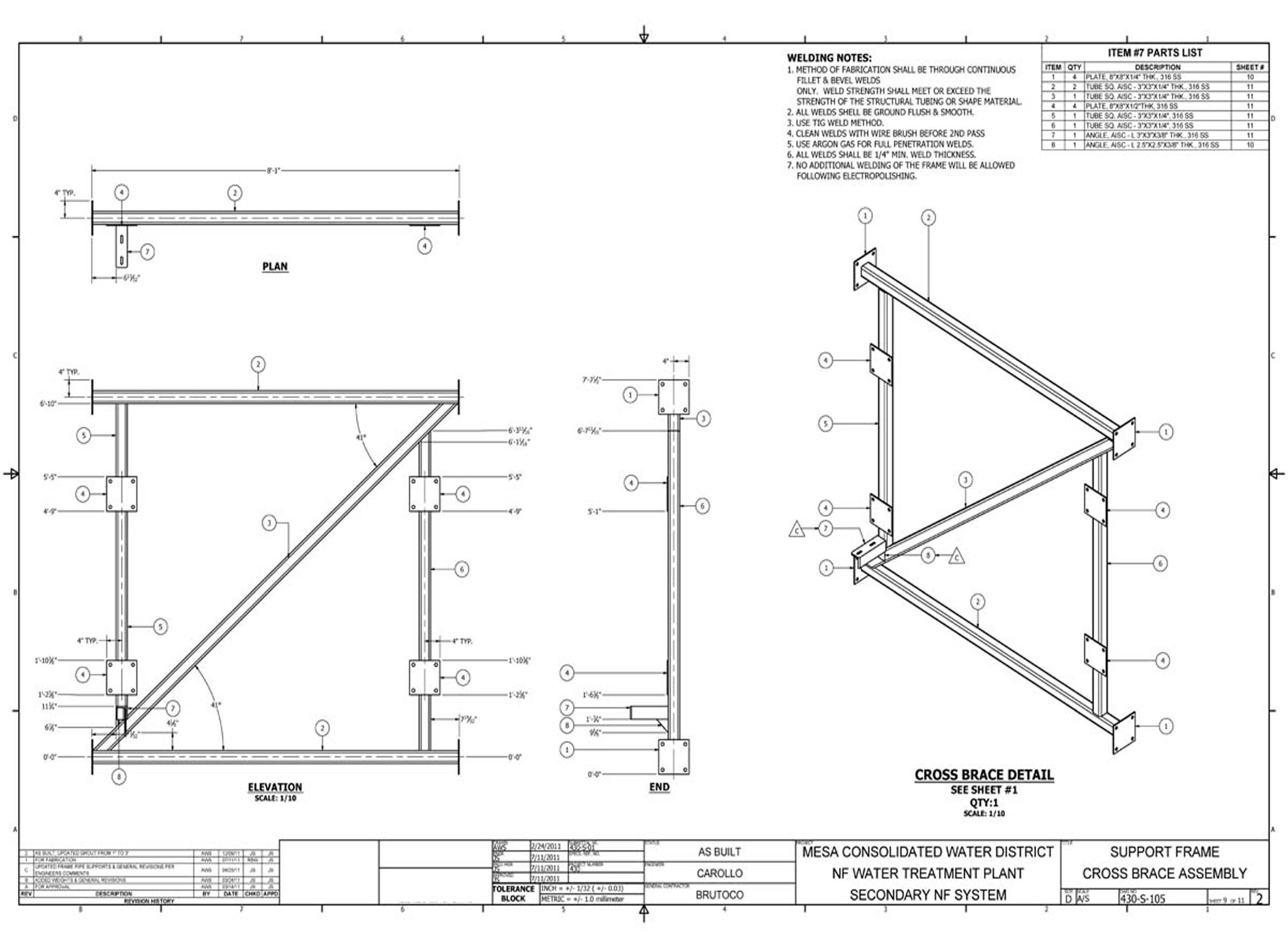
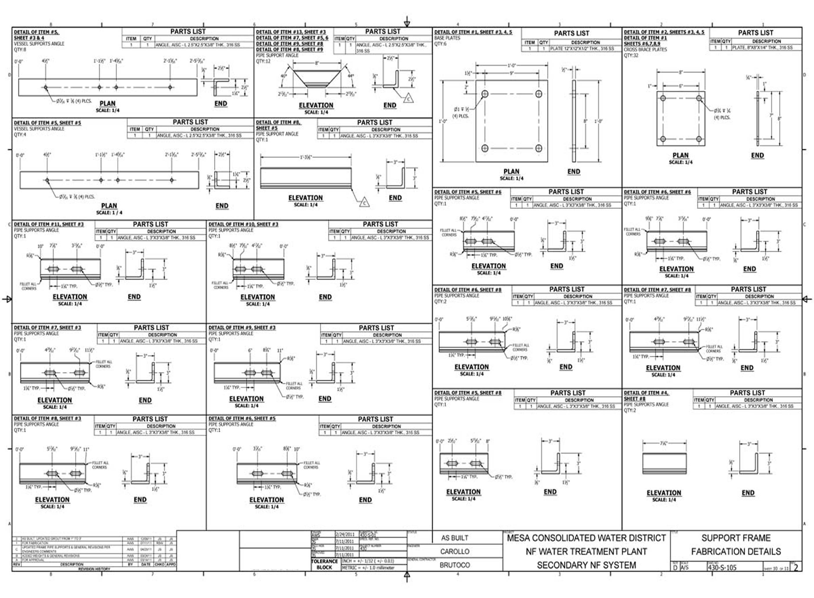
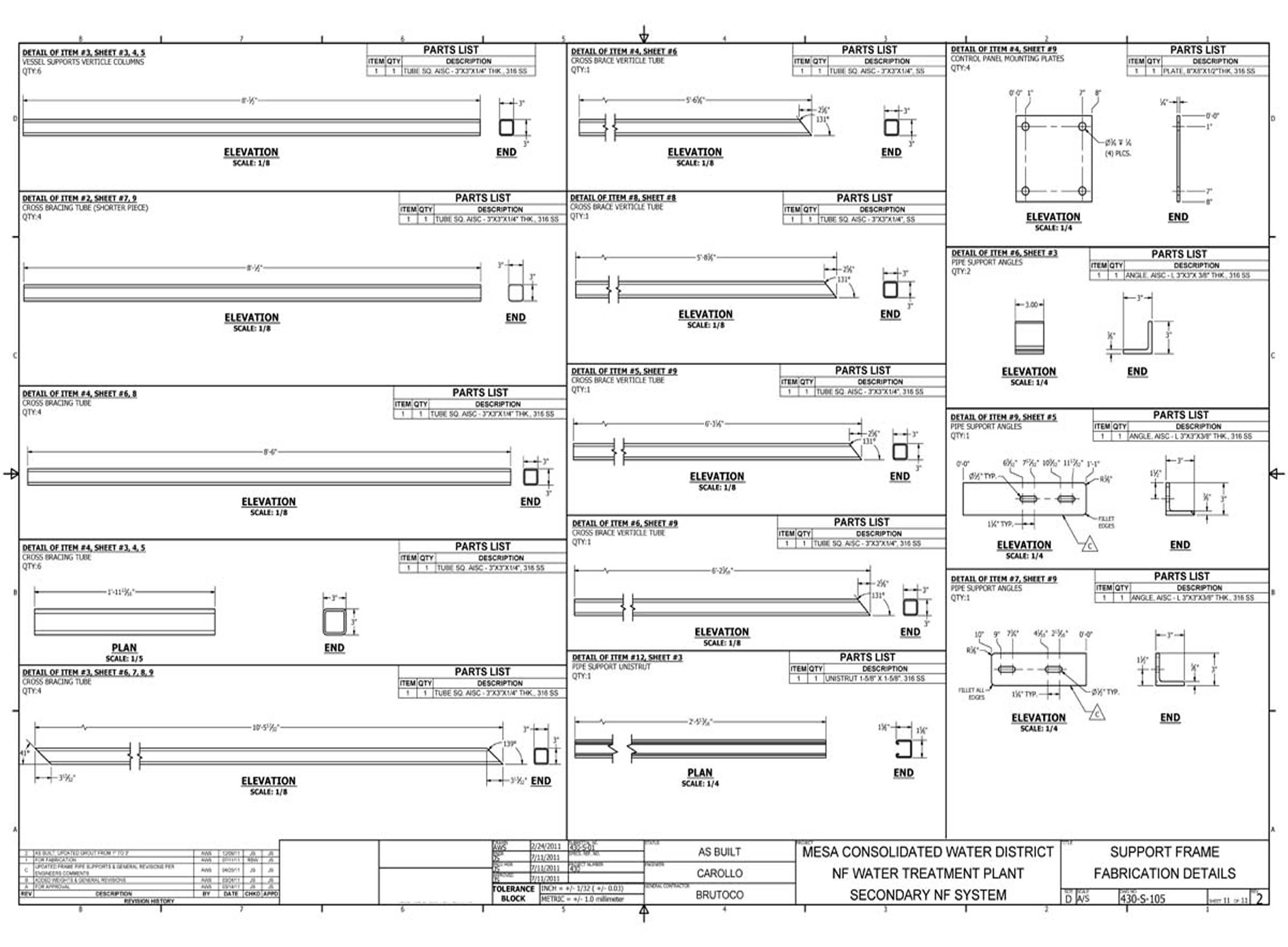
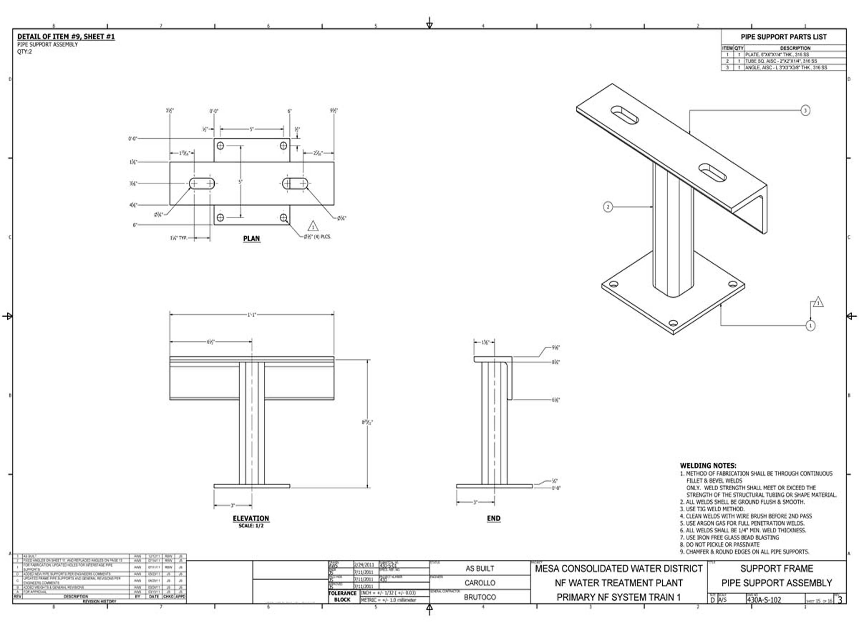
The pipe support detail drawings document the structural clamp assemblies, hanger configurations, and anchorage details for the process piping systems at Costa Mesa. These 2 sheets define the support spacing and load-bearing specifications required for compliant field installation.
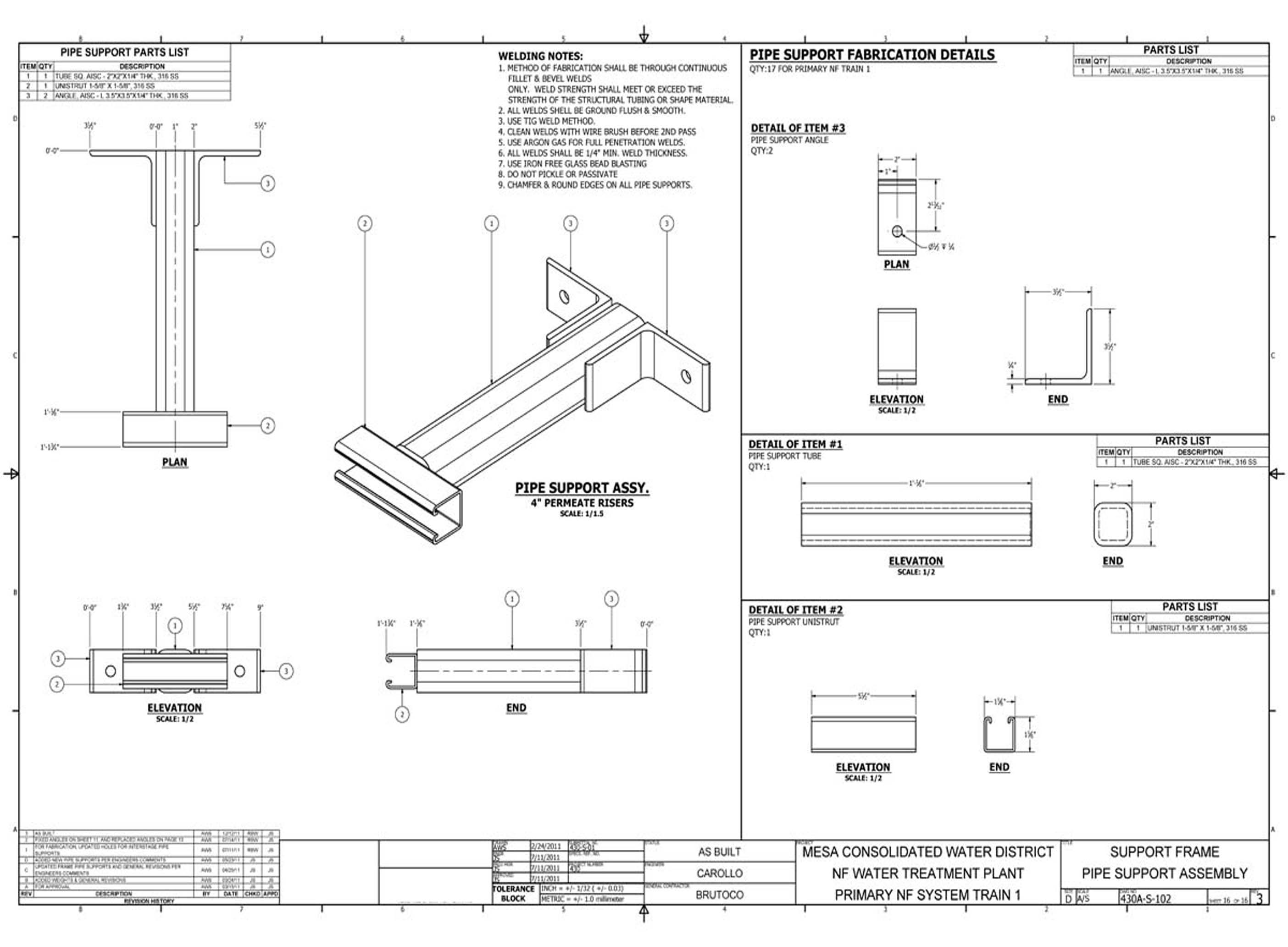
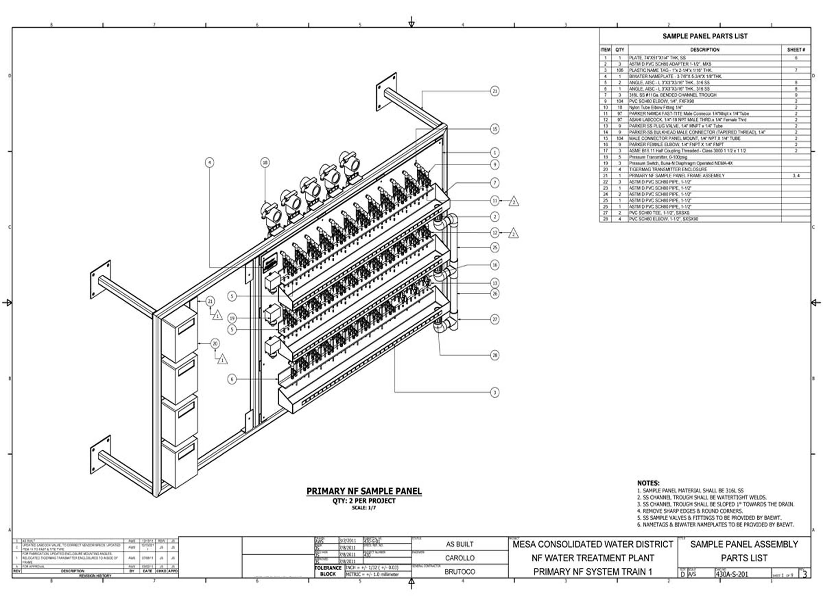
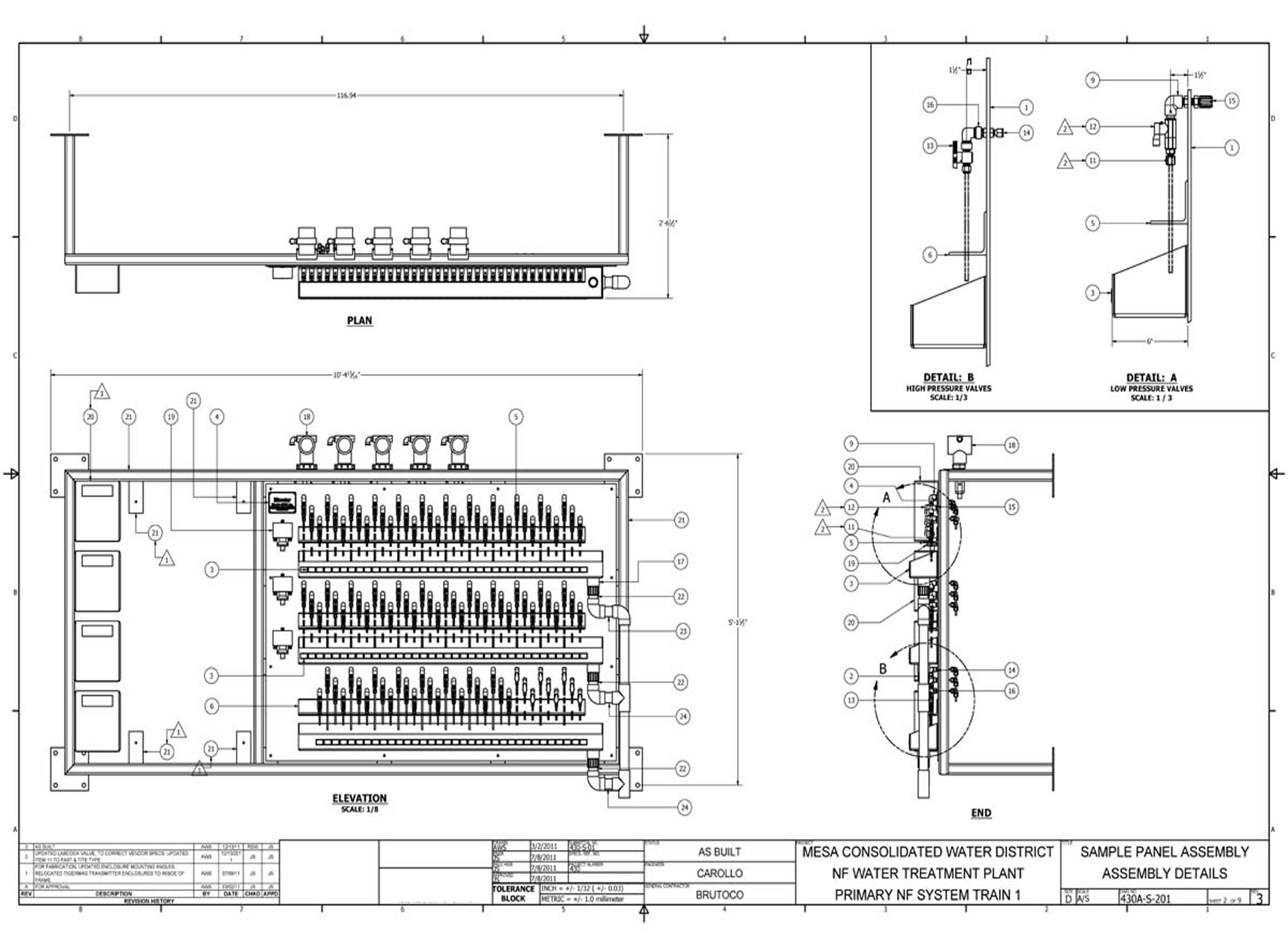
The sampling station drawings document the instrument placement, sample point configurations, and connection details for the water quality monitoring assemblies at Costa Mesa. These 17 sheets define the sample tap locations and flow paths required for accurate process monitoring throughout the treatment system.
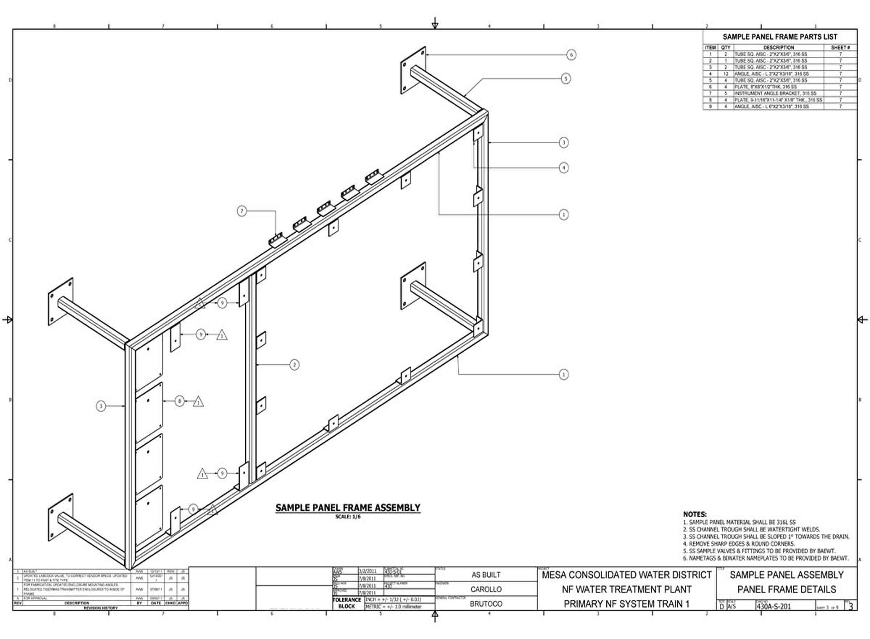
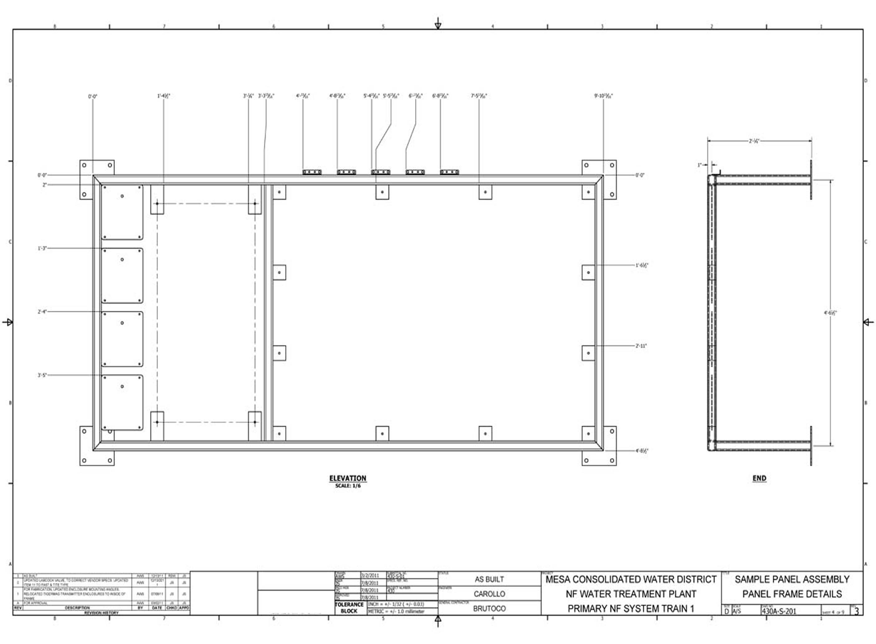
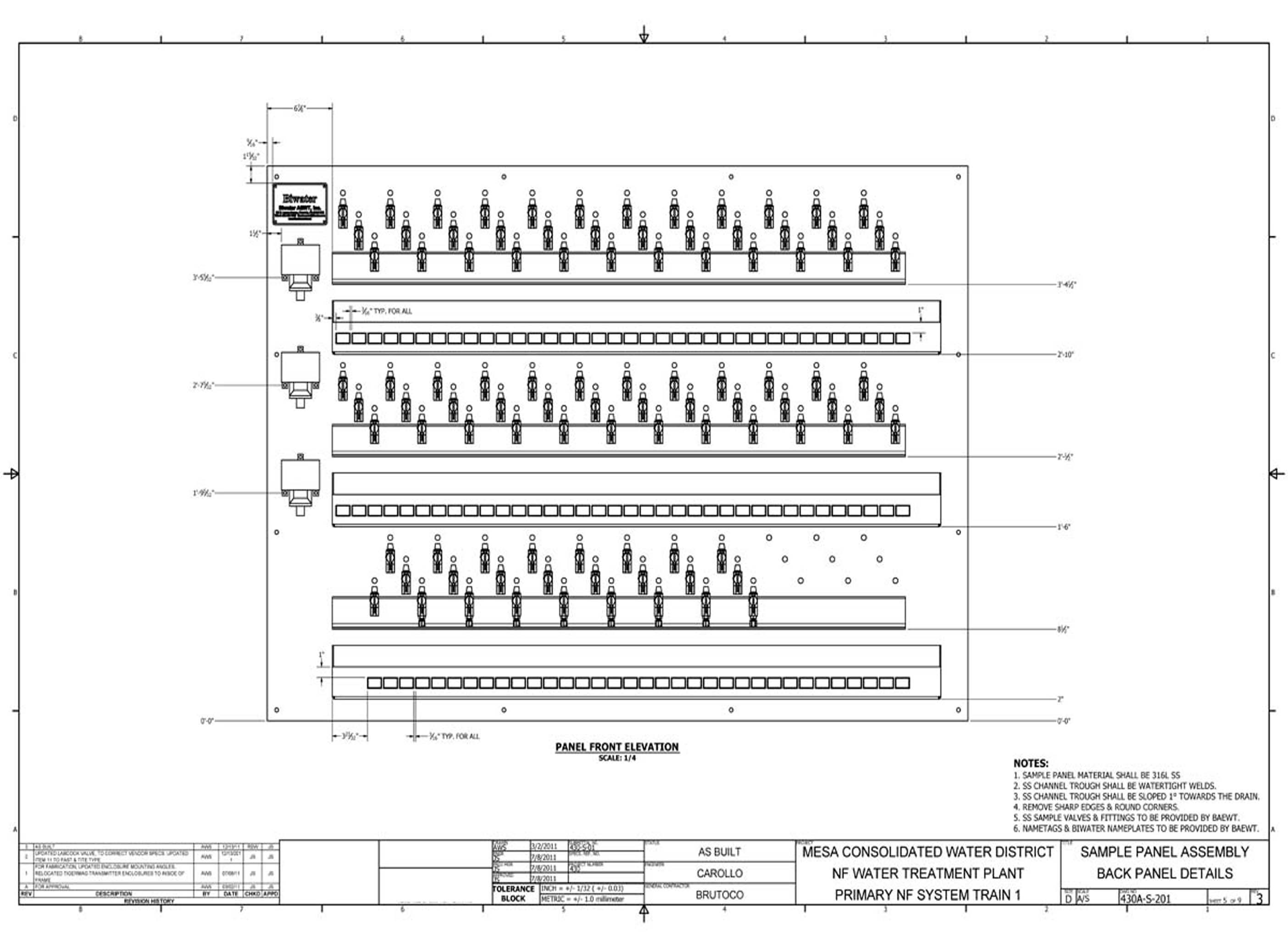
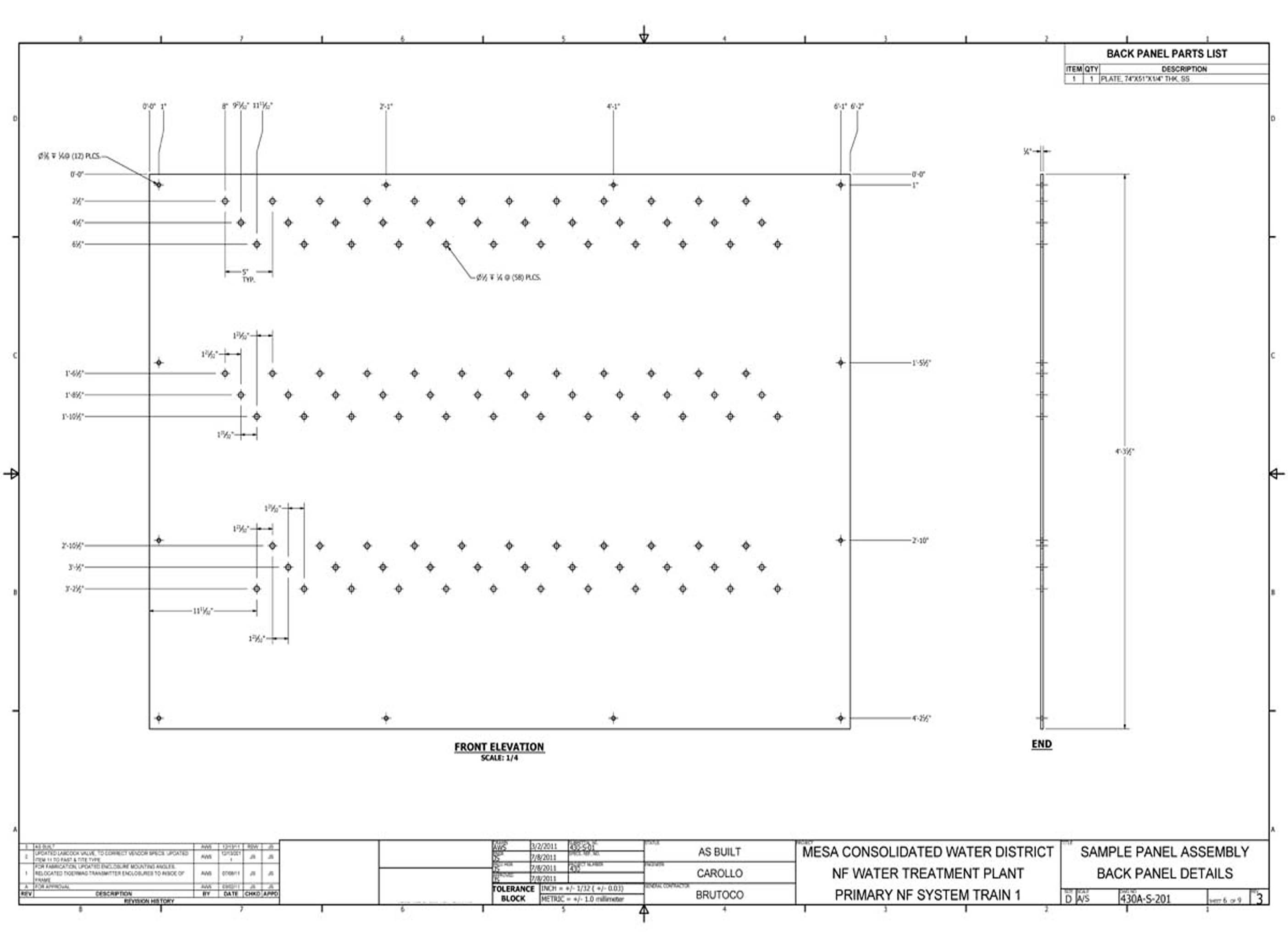
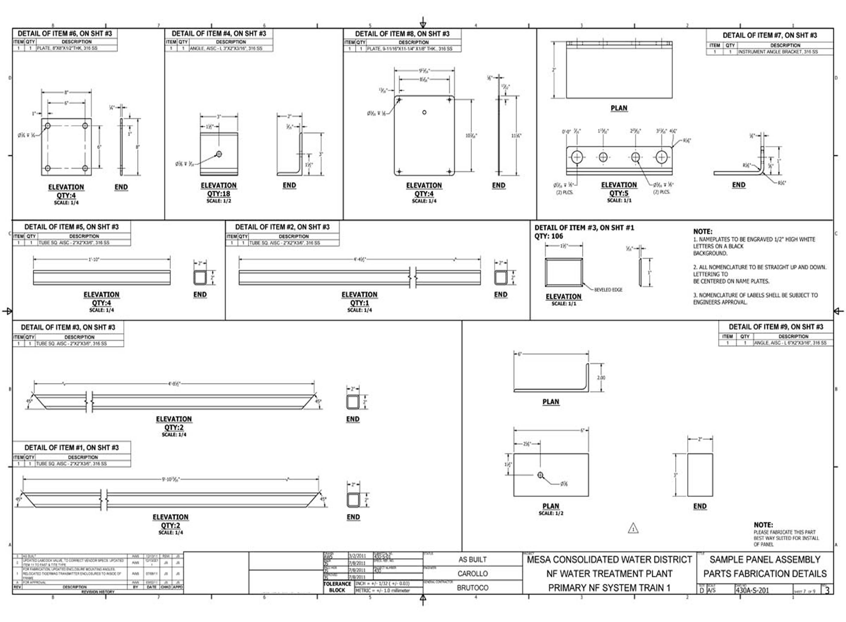
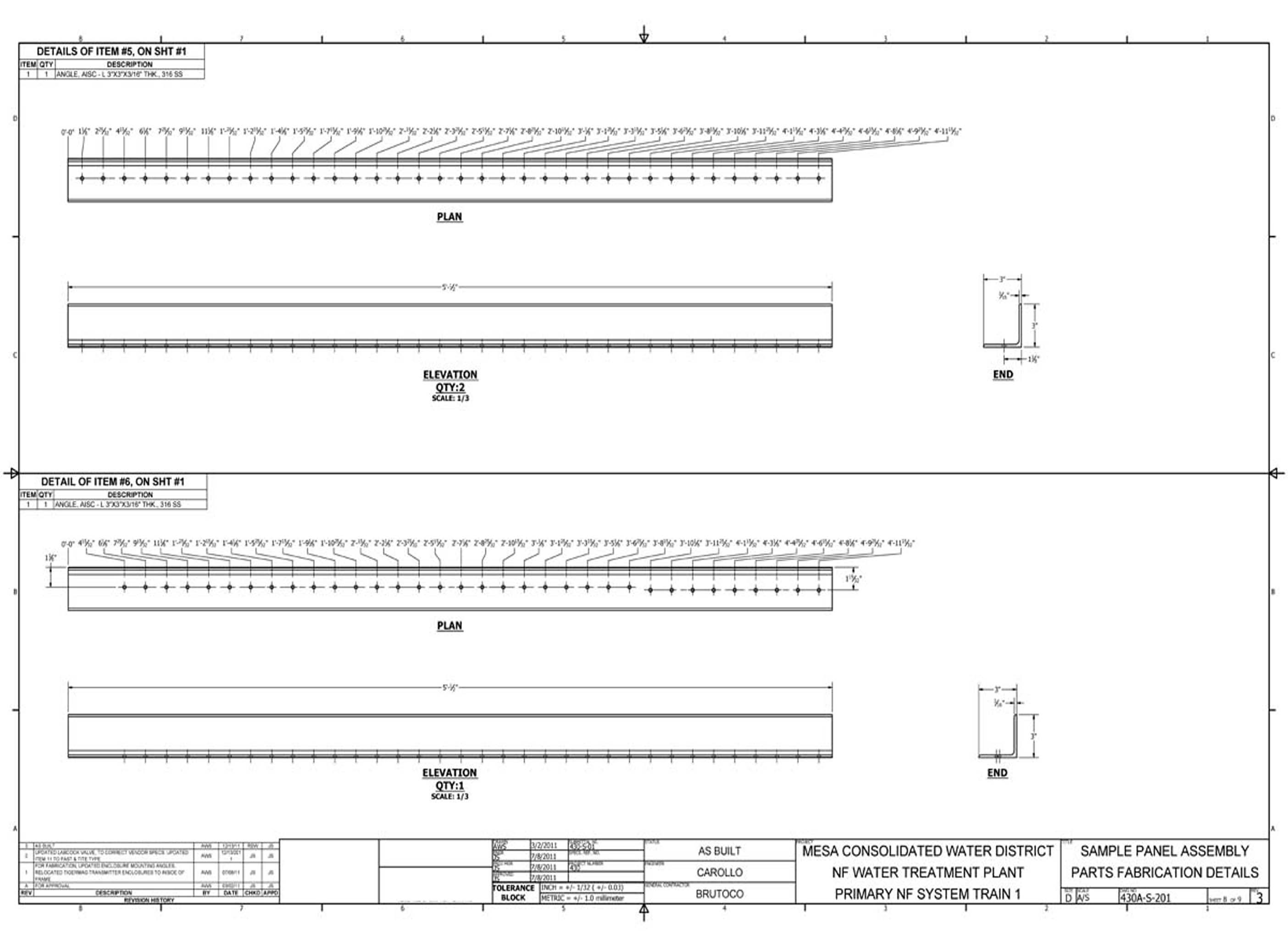
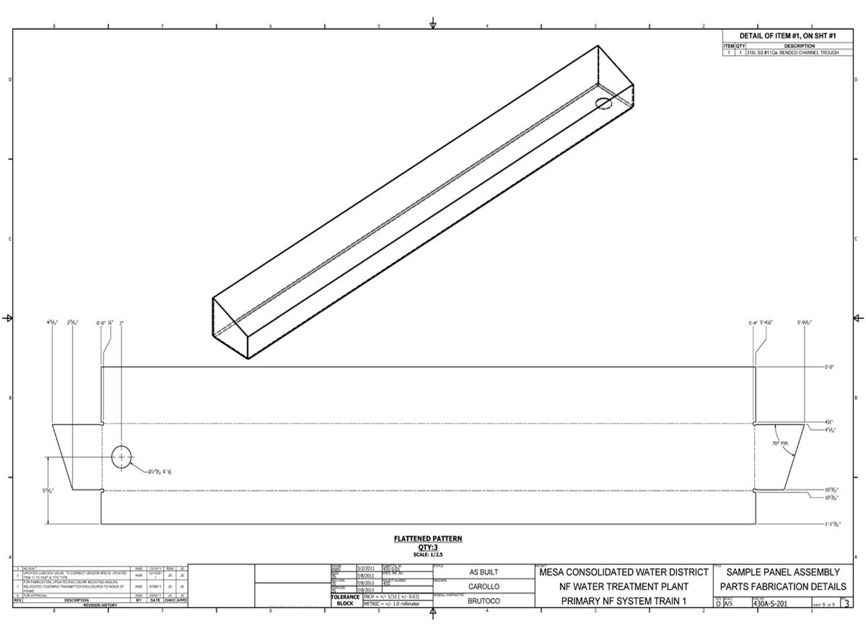
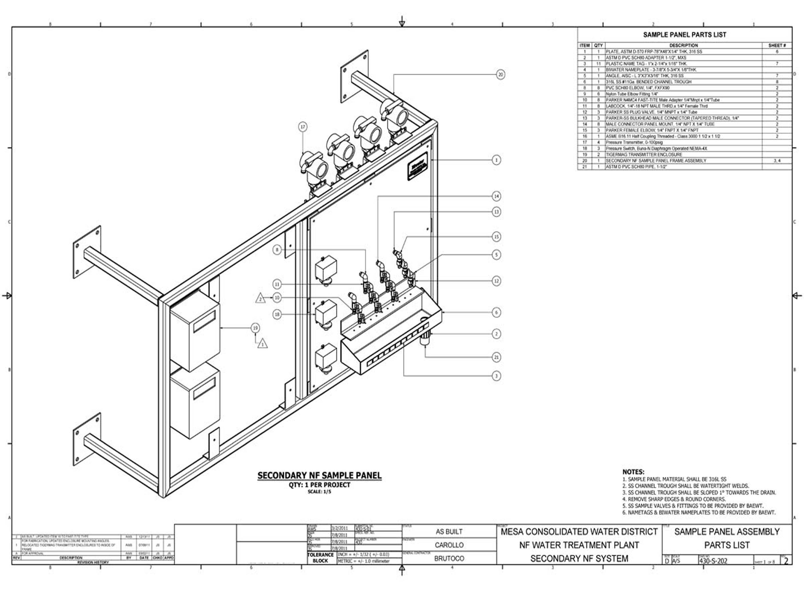
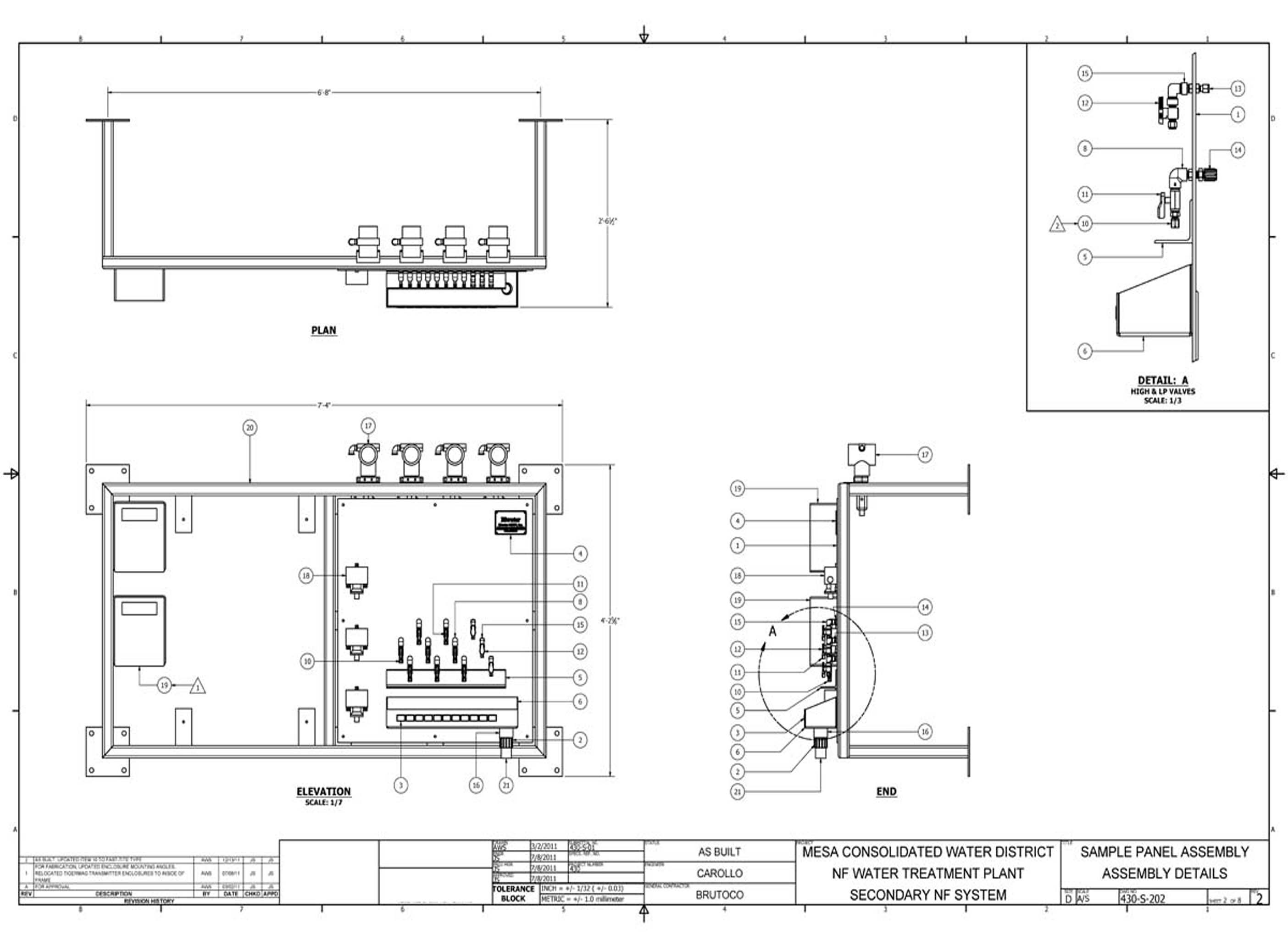
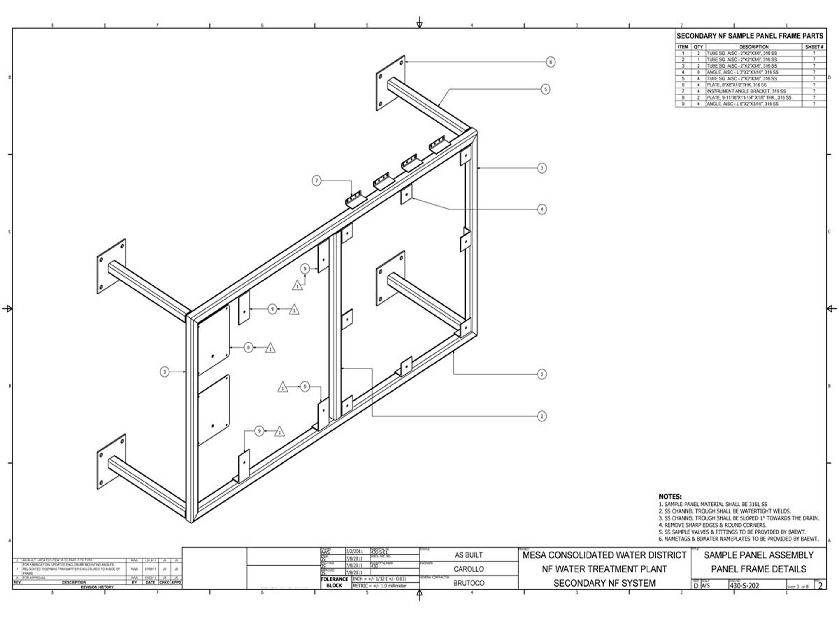
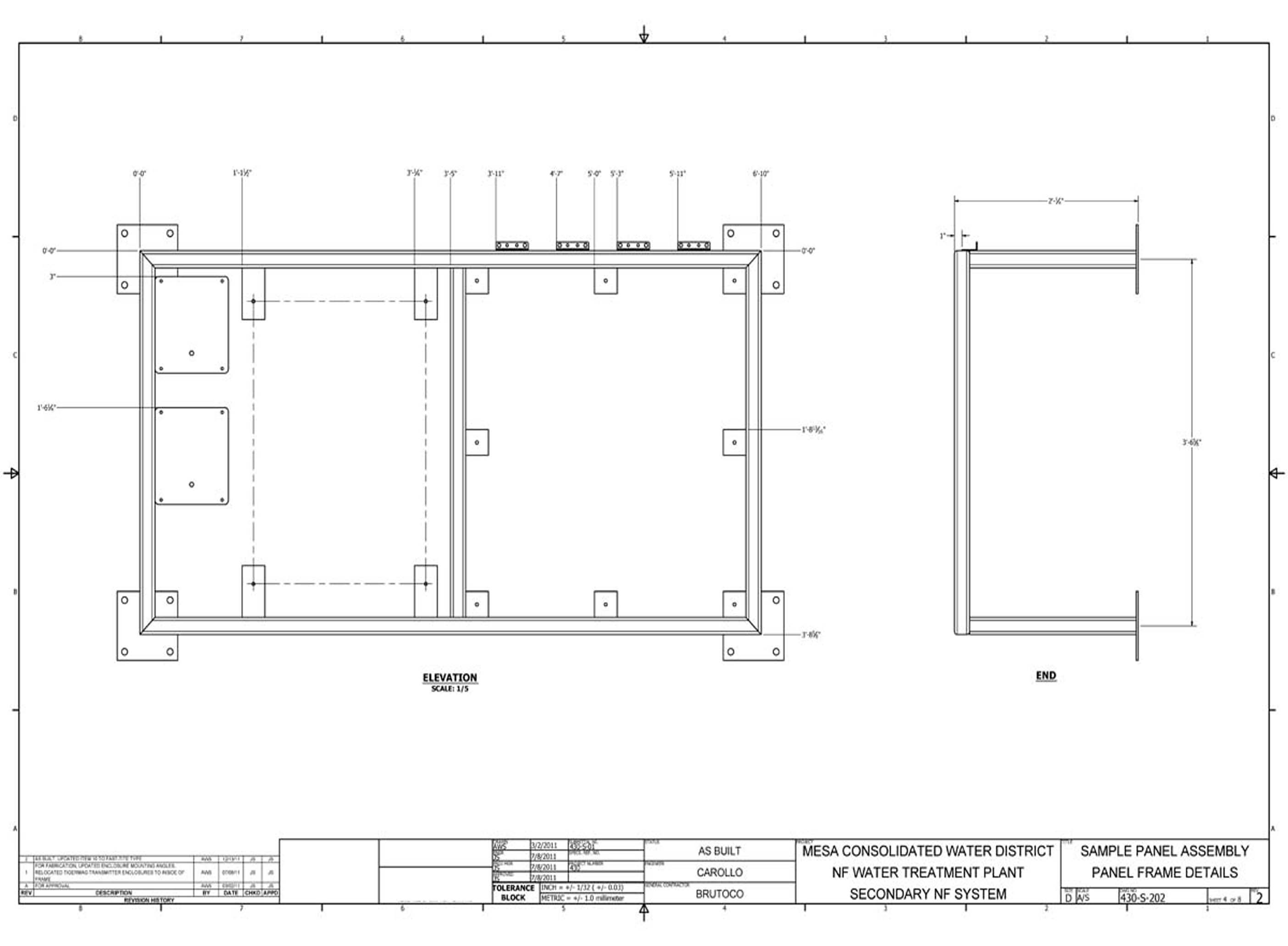
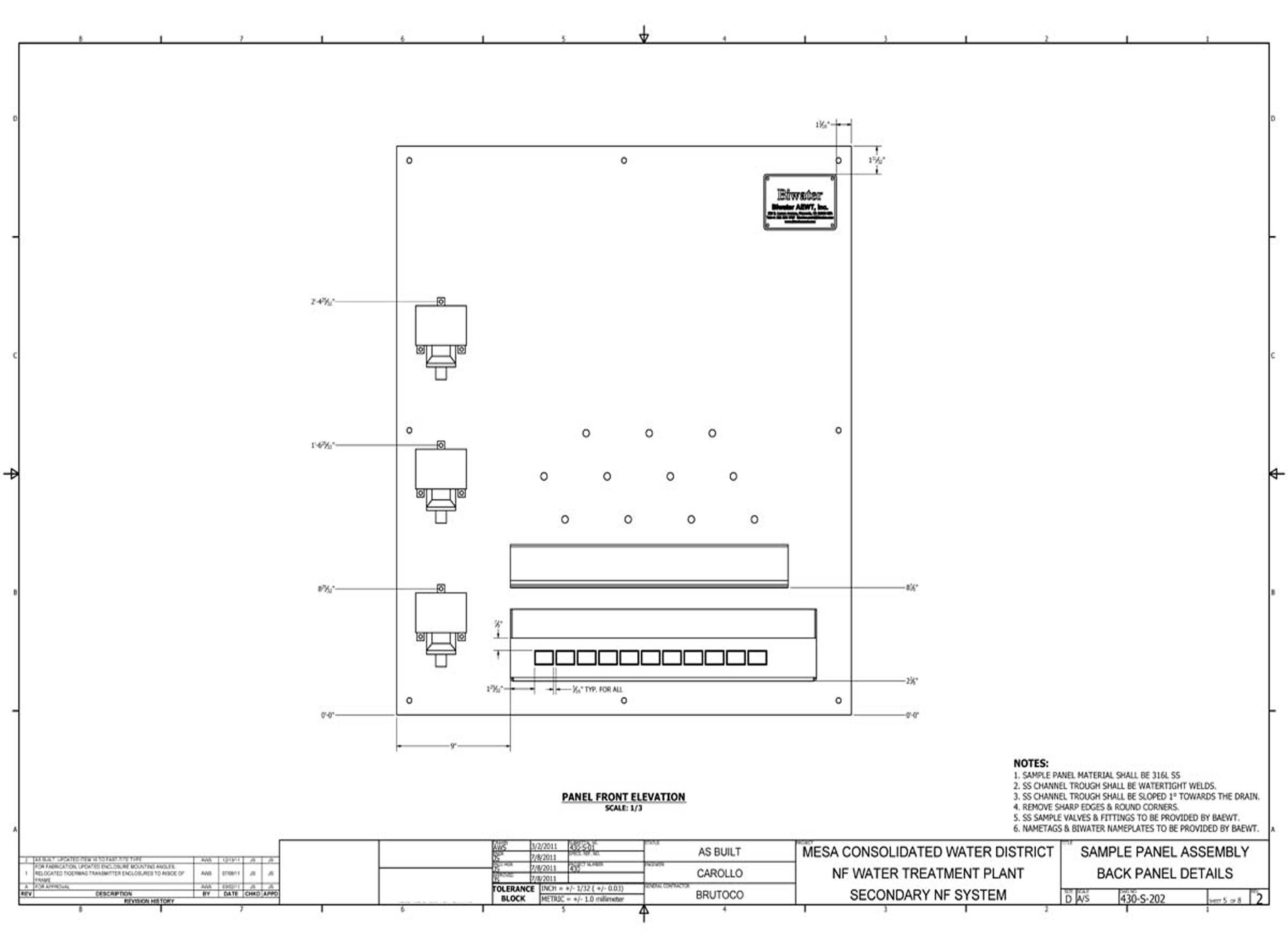
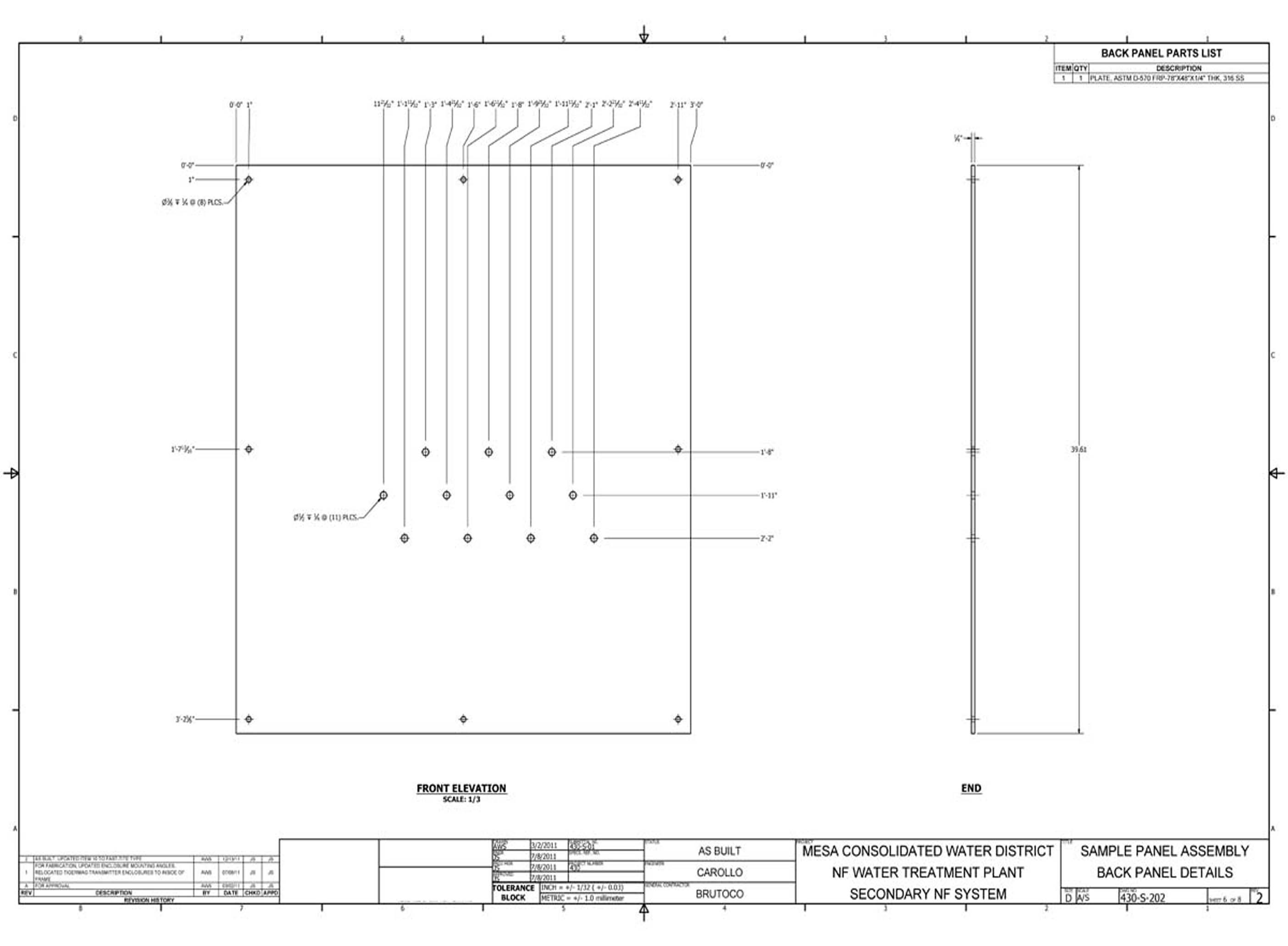
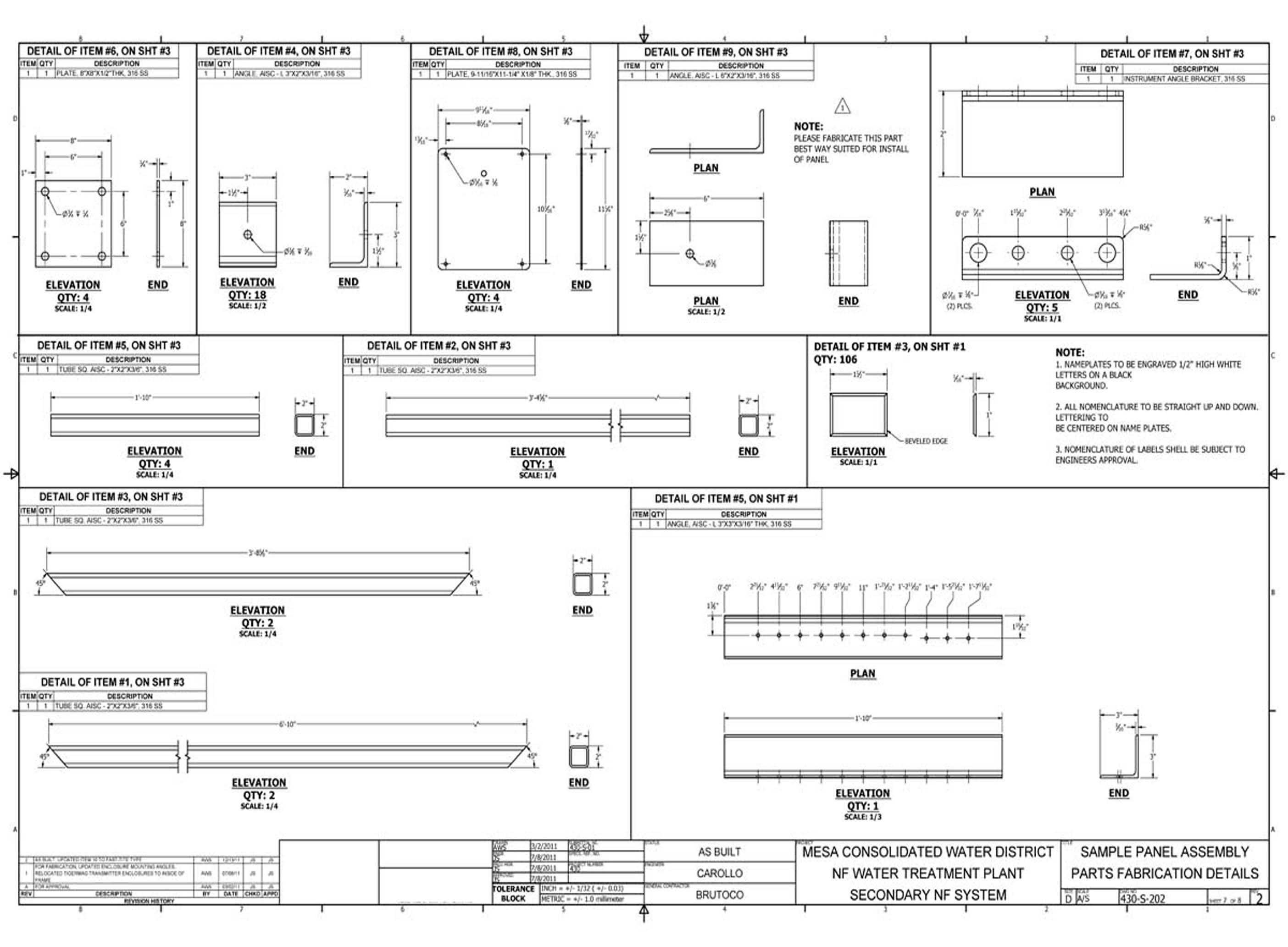
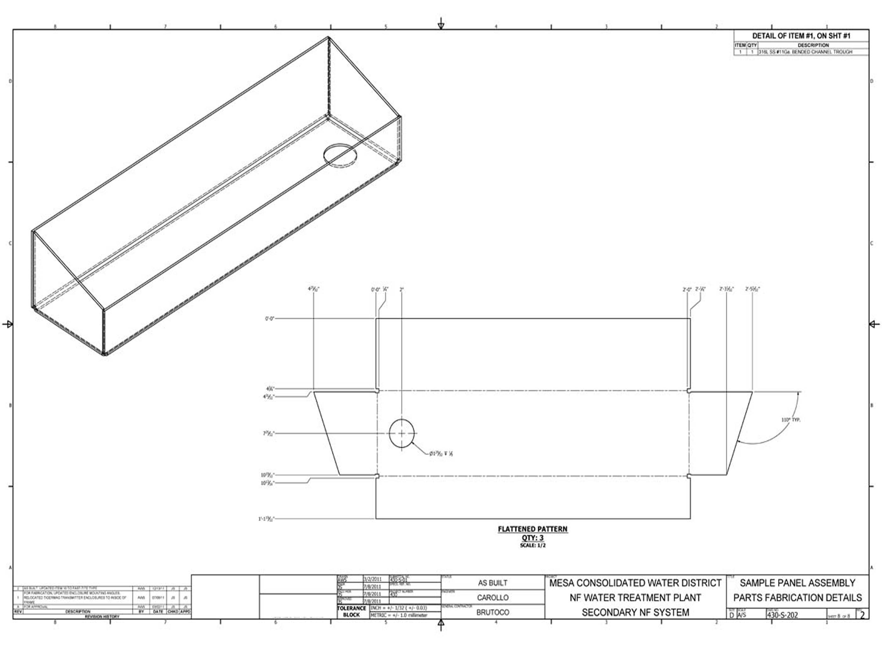
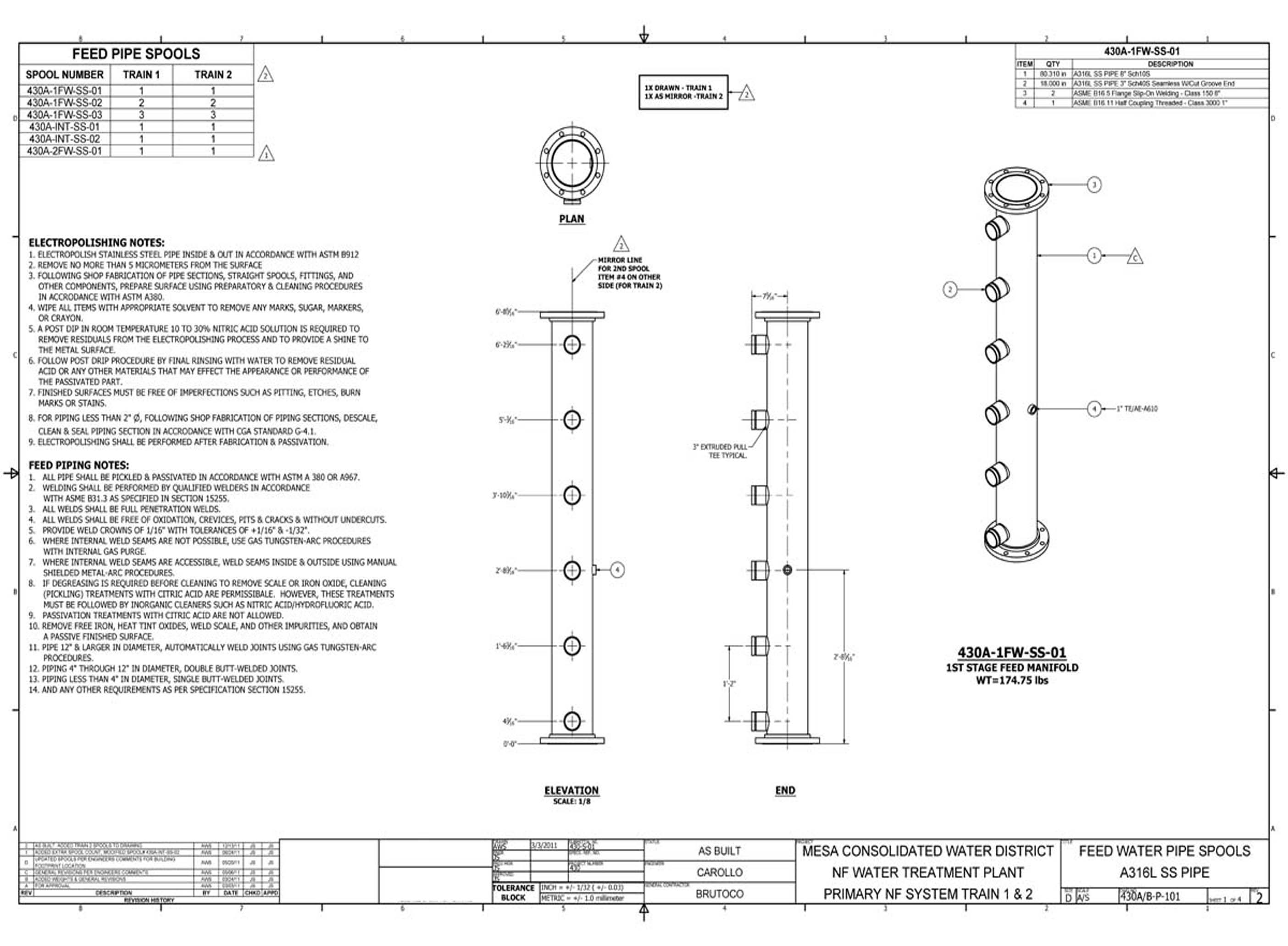
The primary pipe spool drawings define 27 individual piping assemblies for the main process circuits of the Costa Mesa treatment system. Developed in Autodesk Inventor, these sheets provide the dimensional, material, and weld specification data required for shop fabrication and field installation of the primary piping.
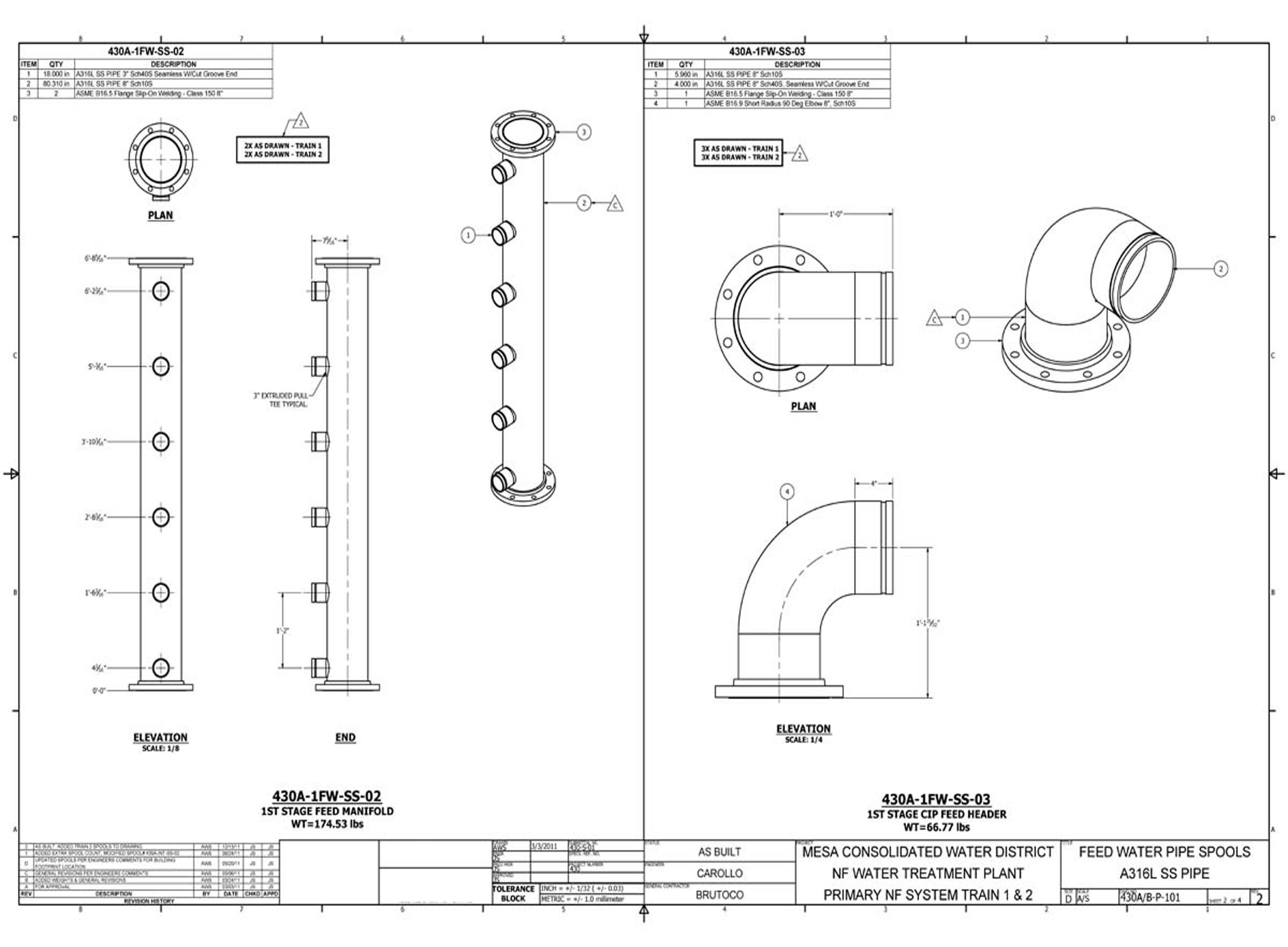
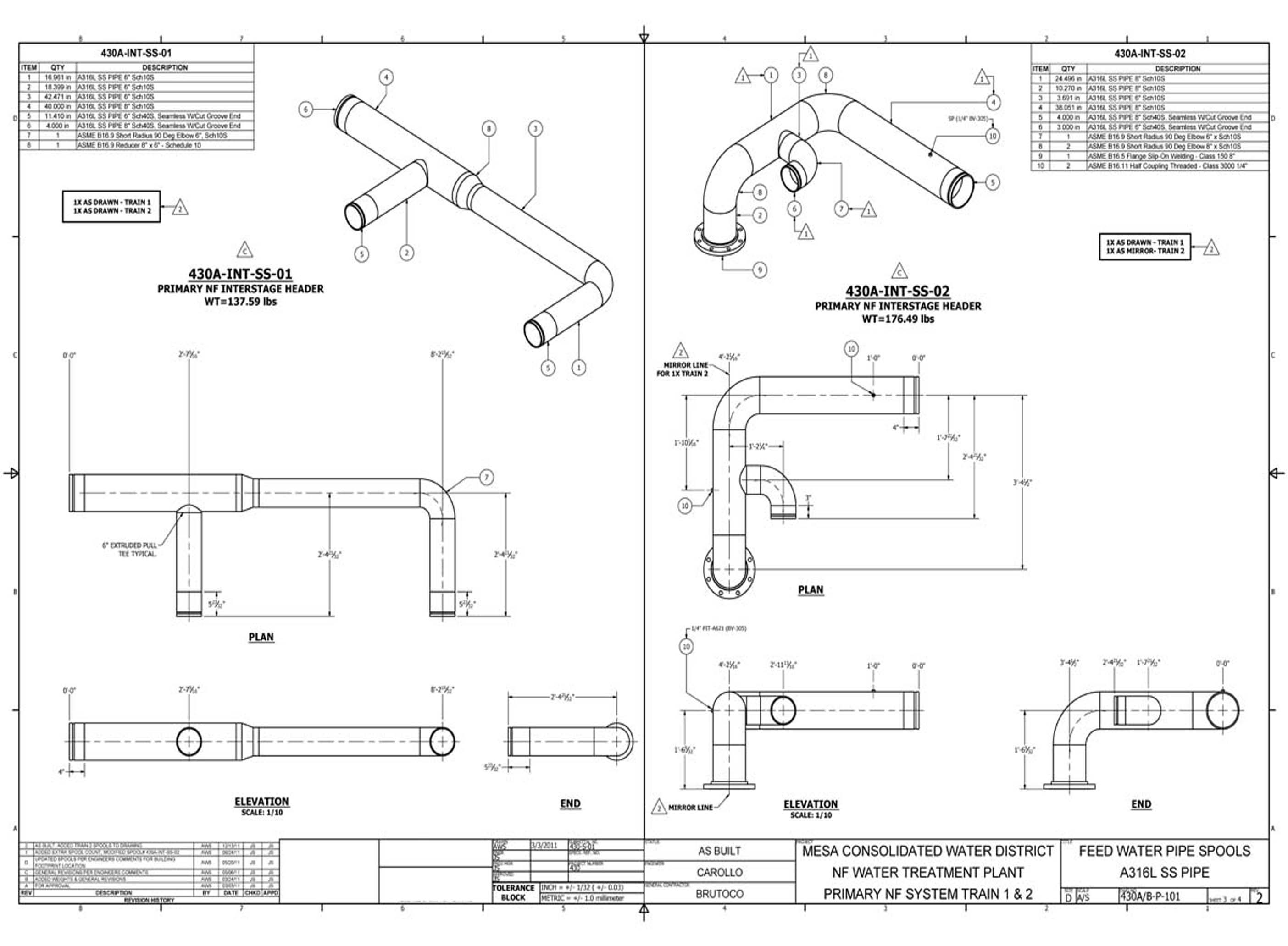
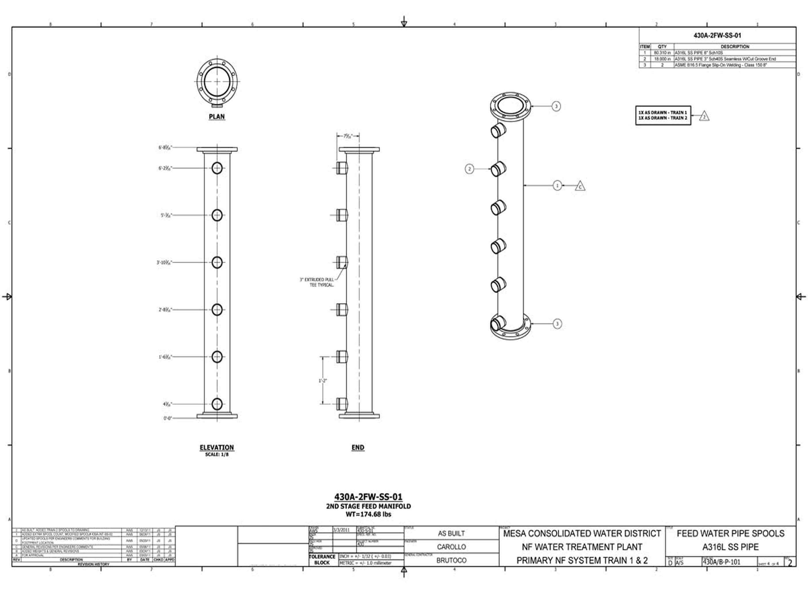
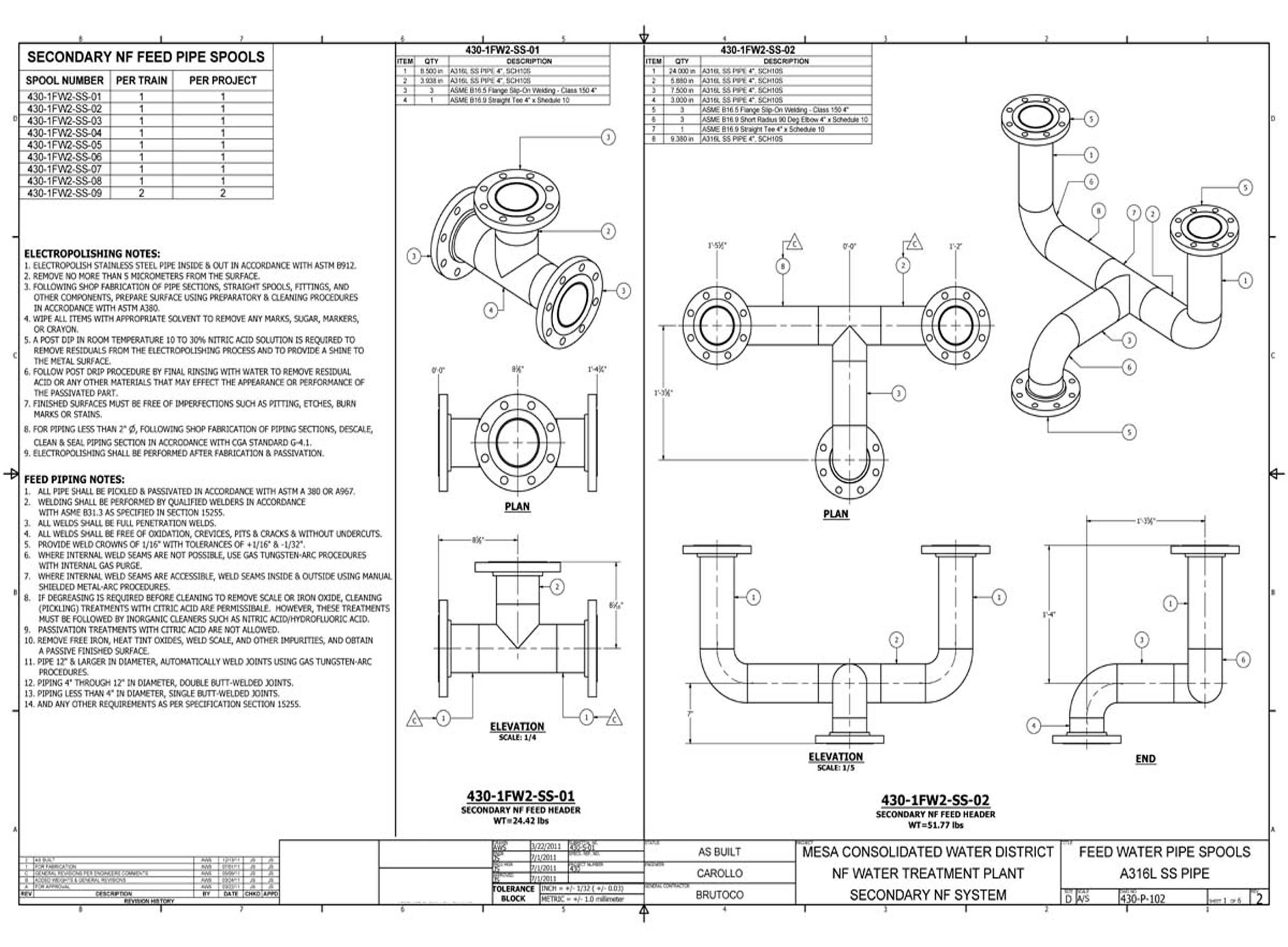
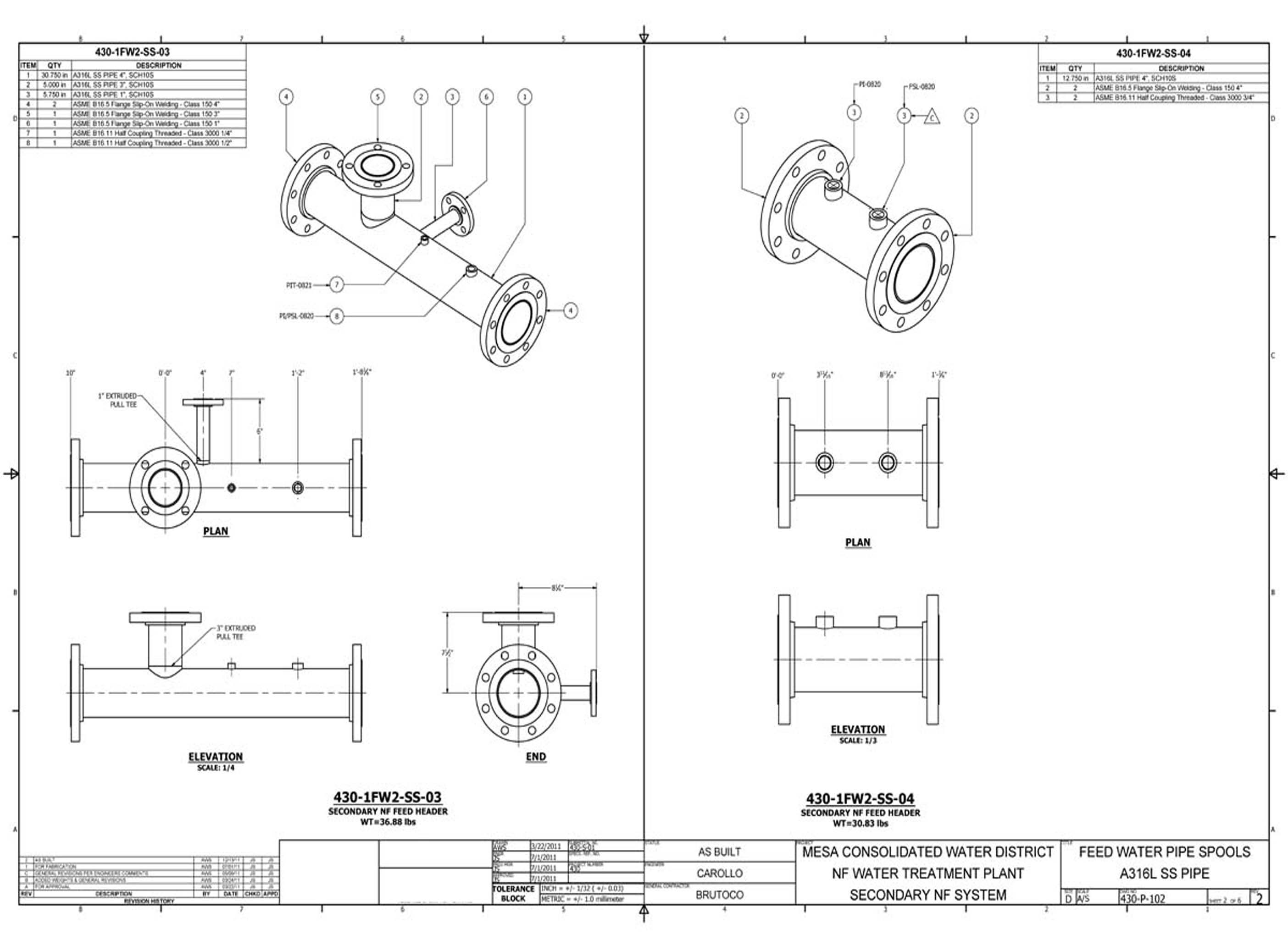
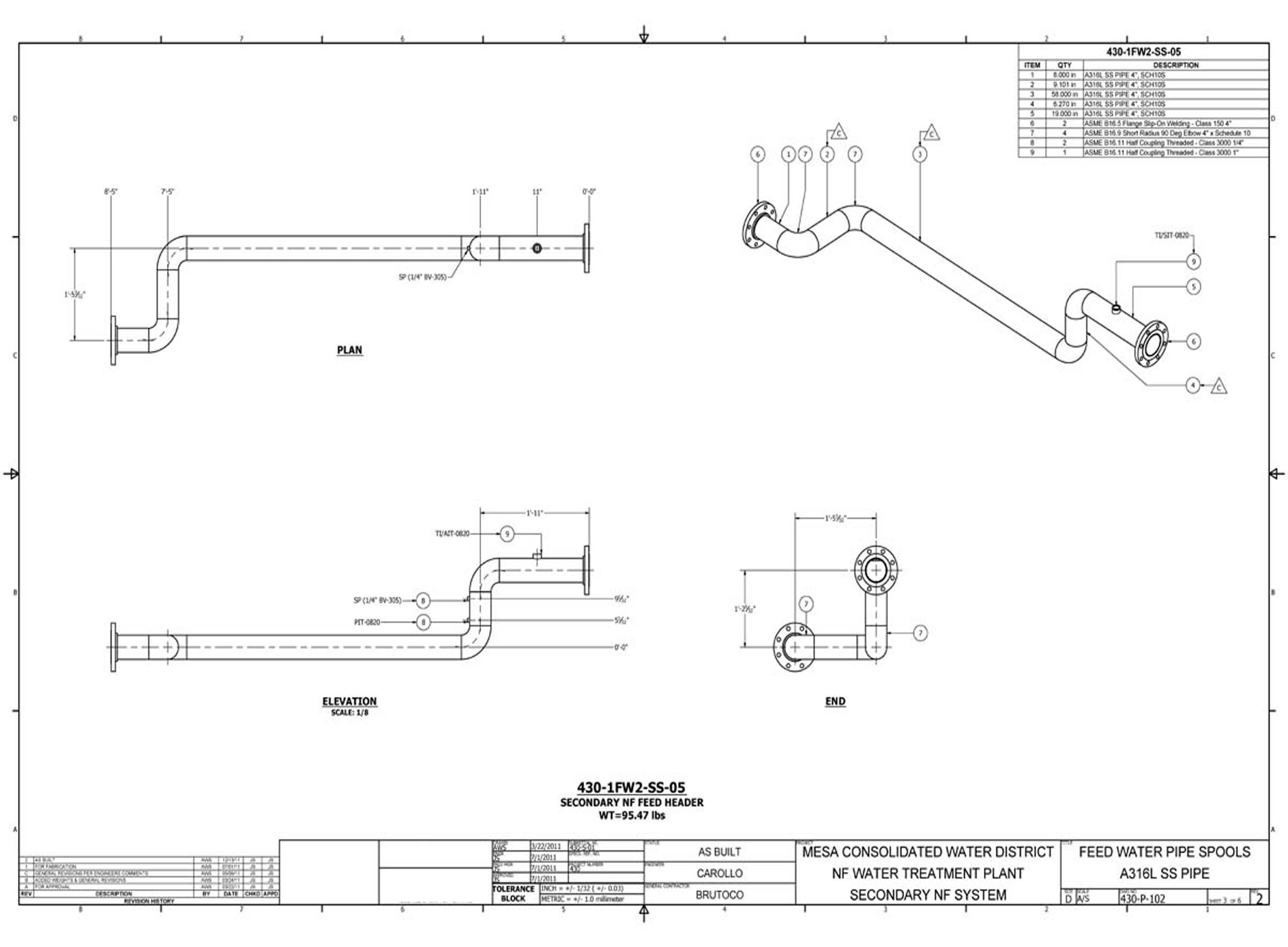
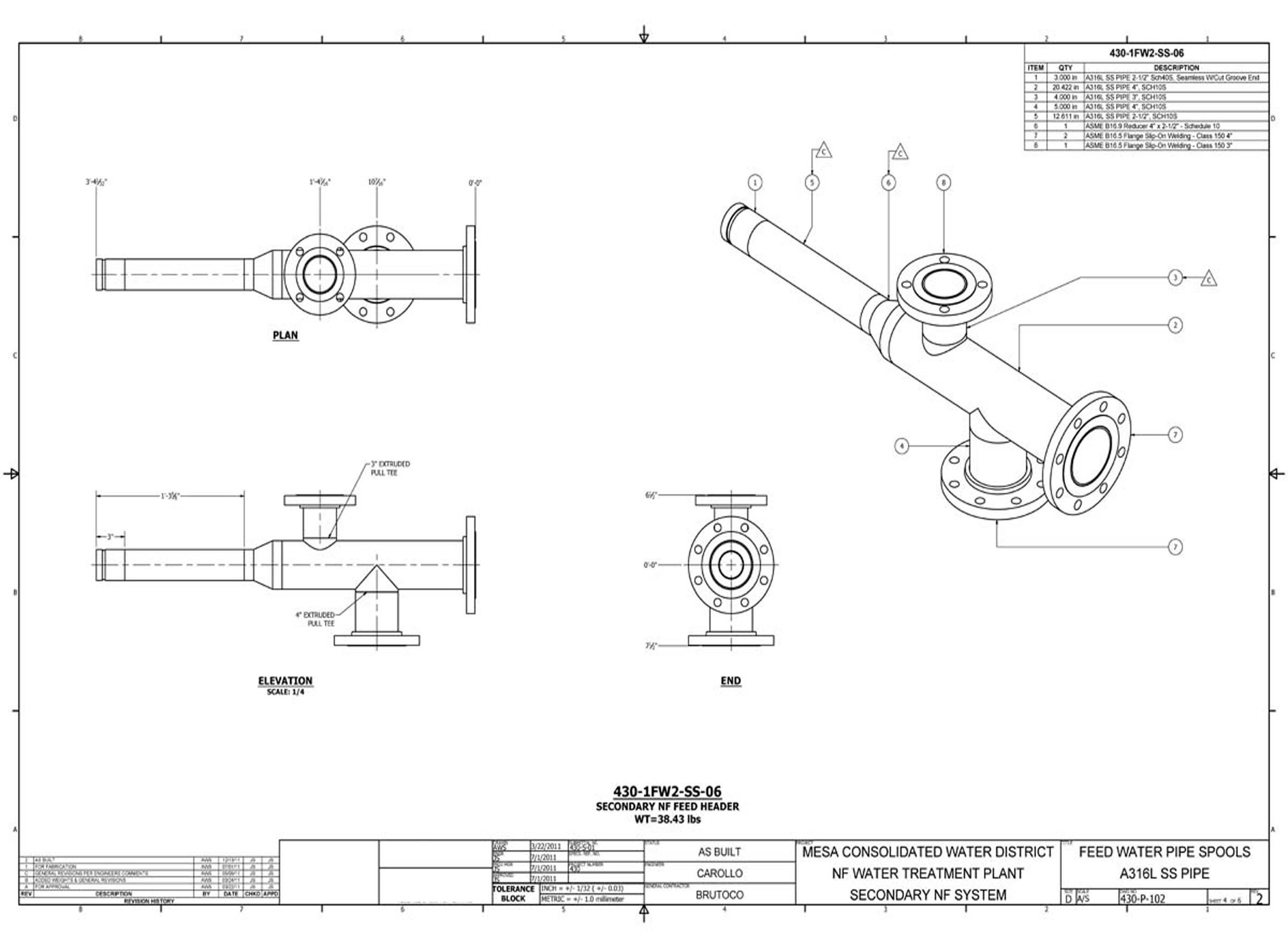
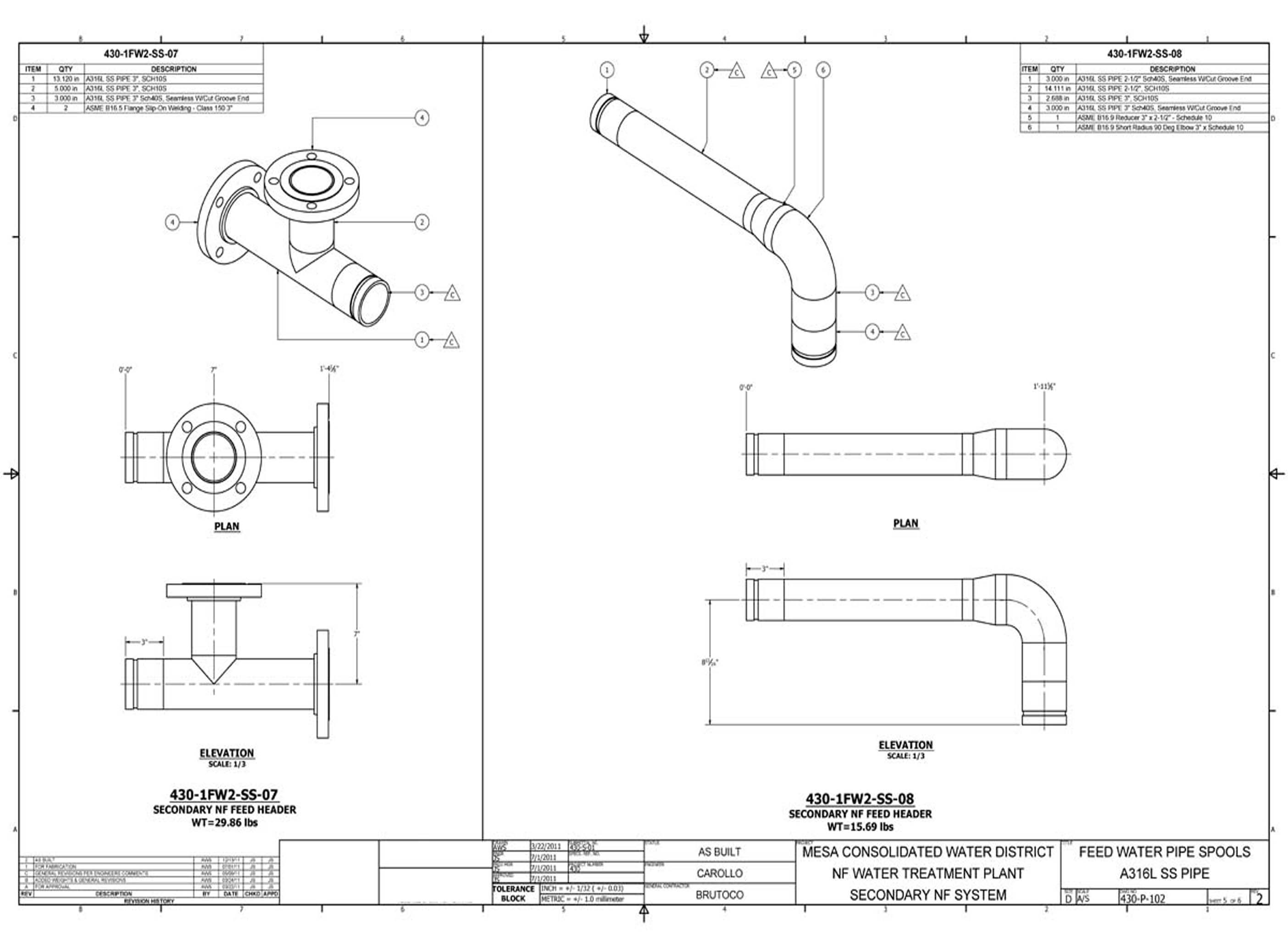
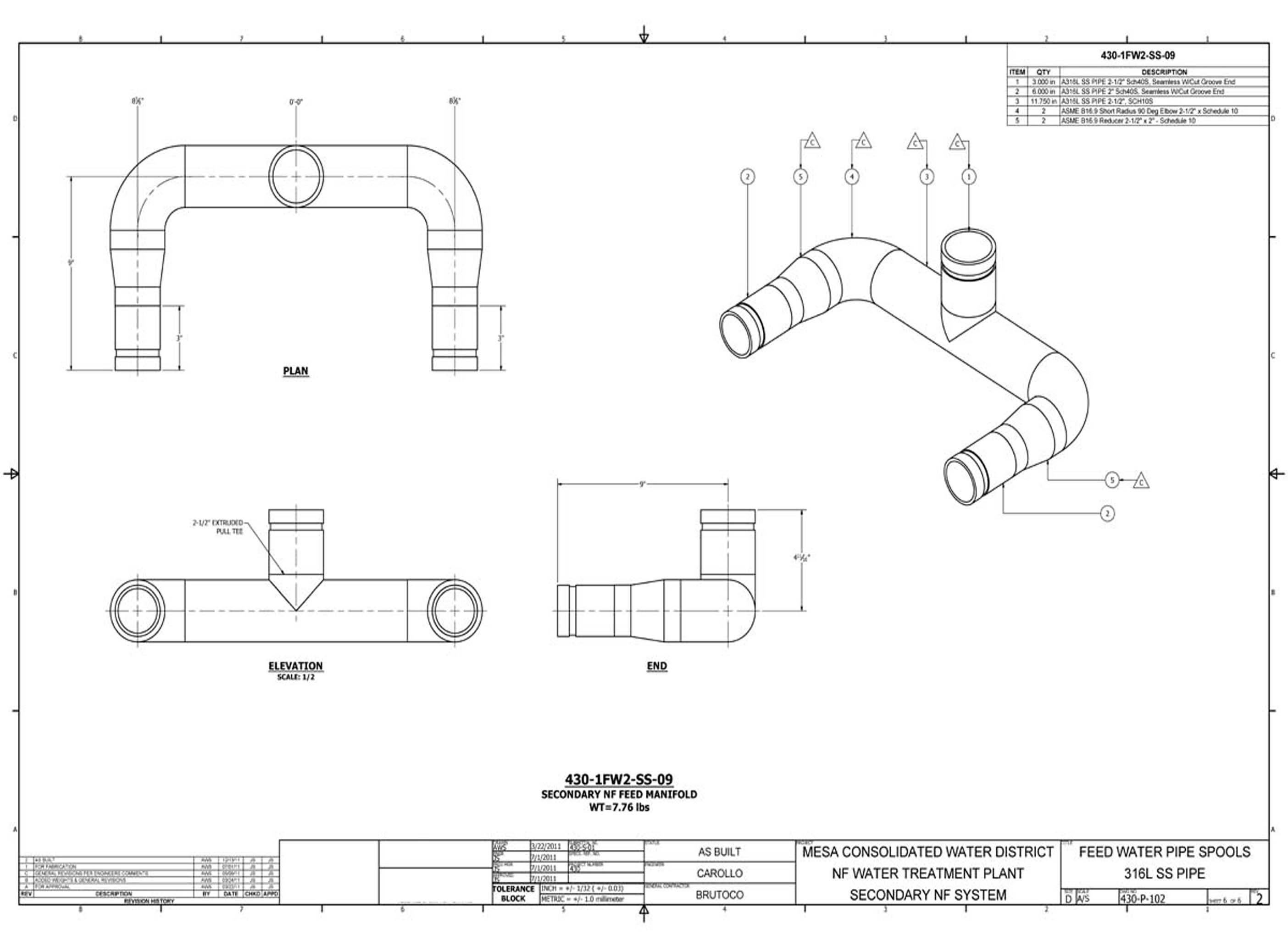
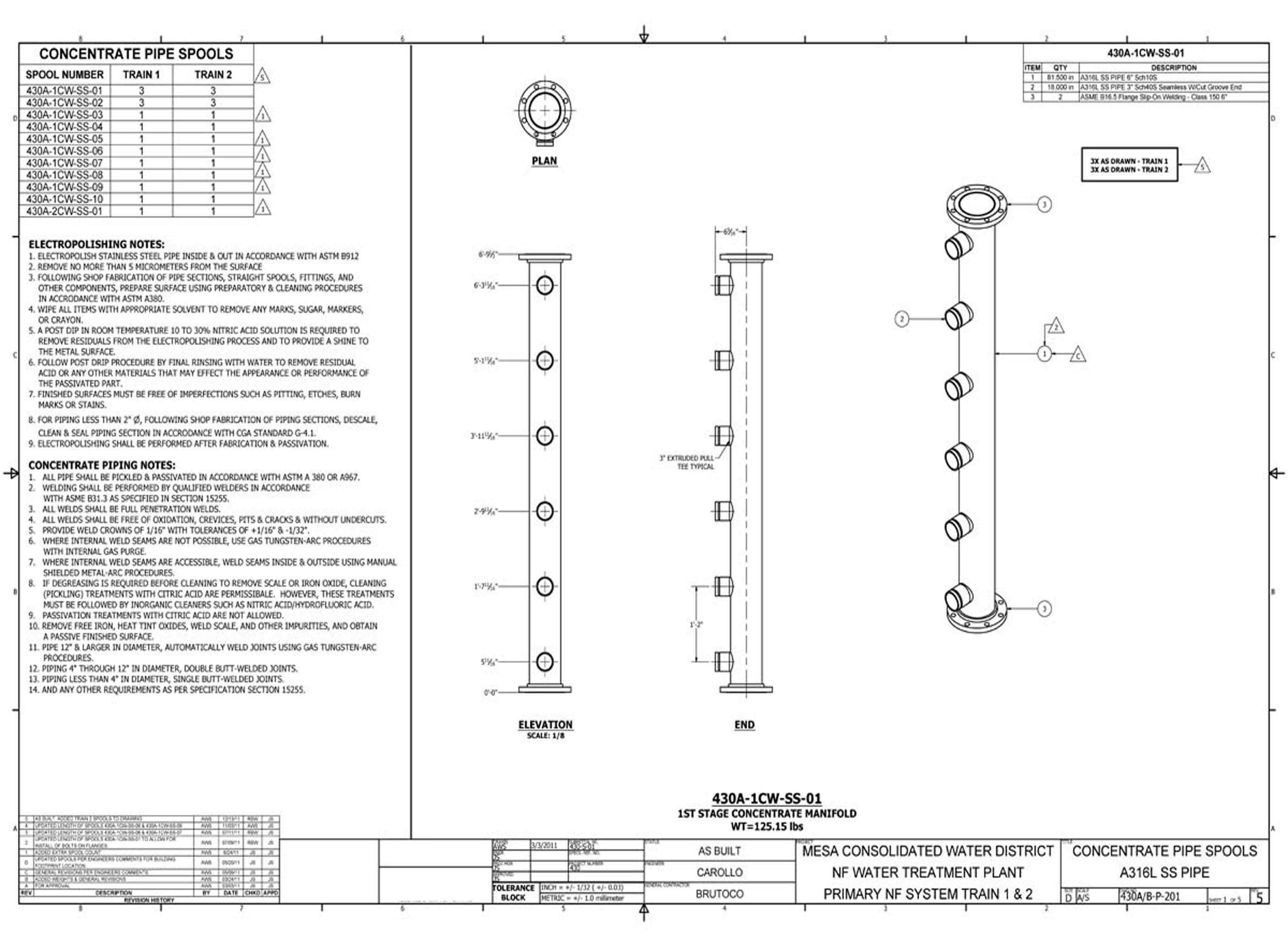
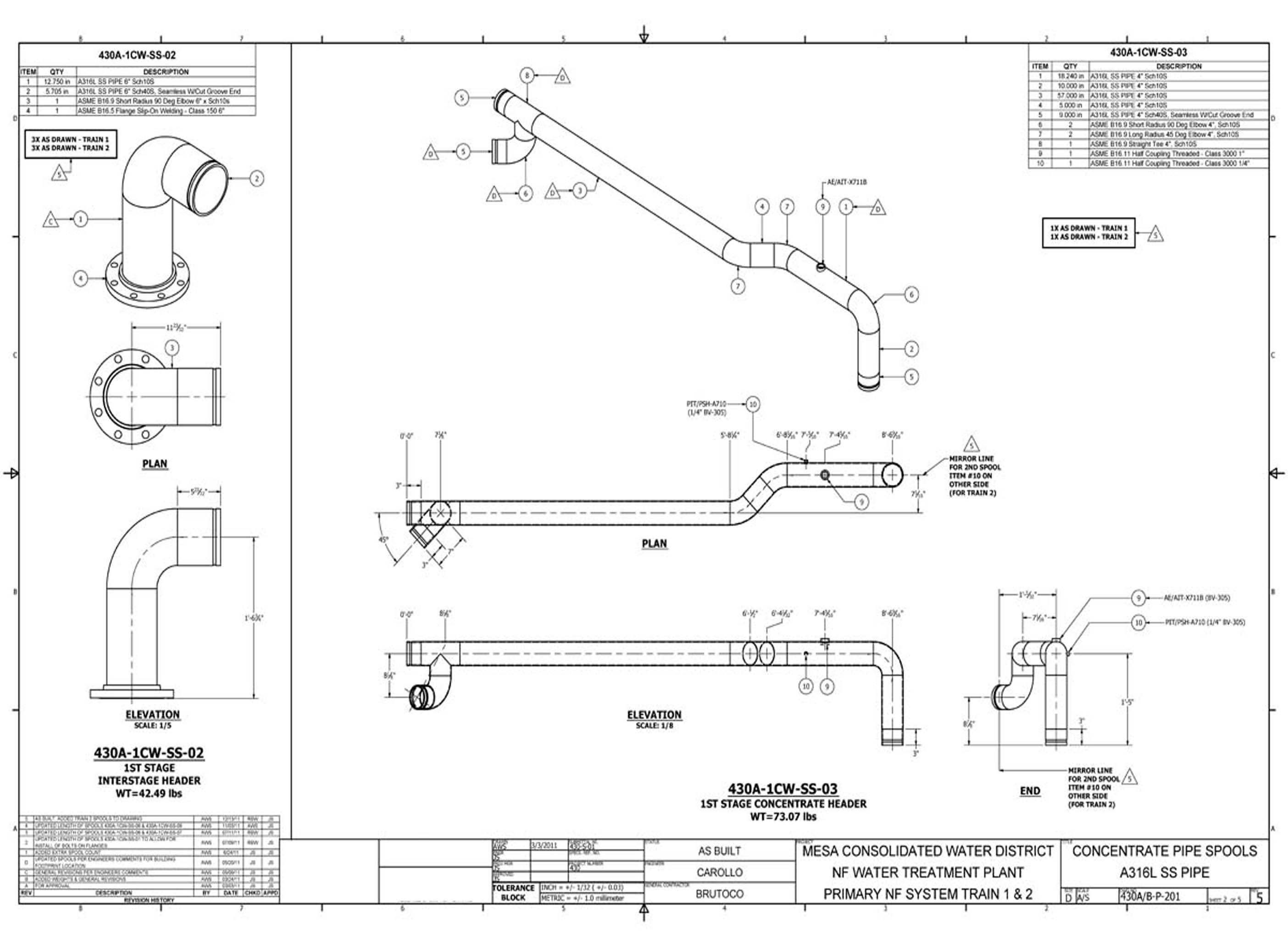
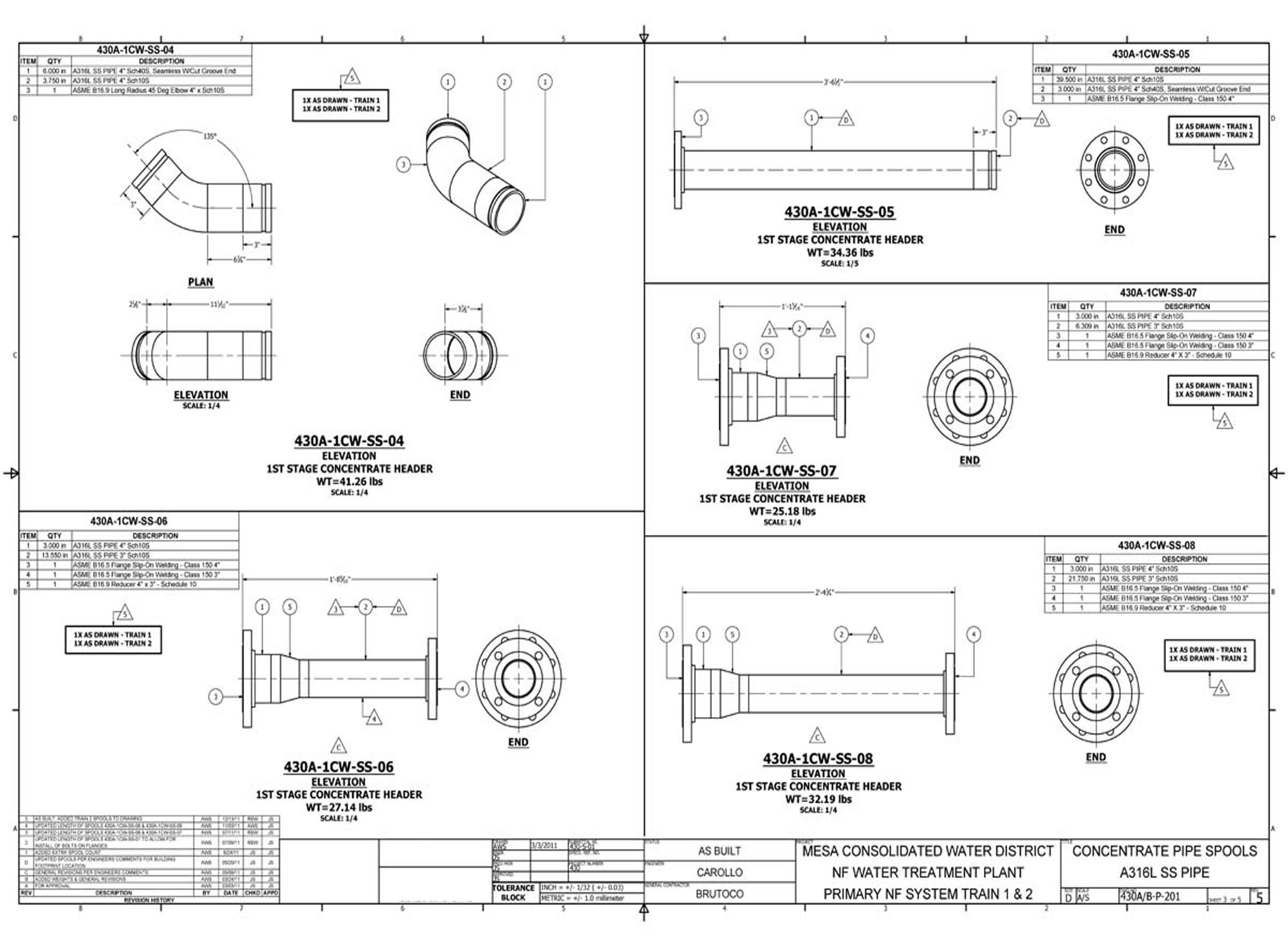
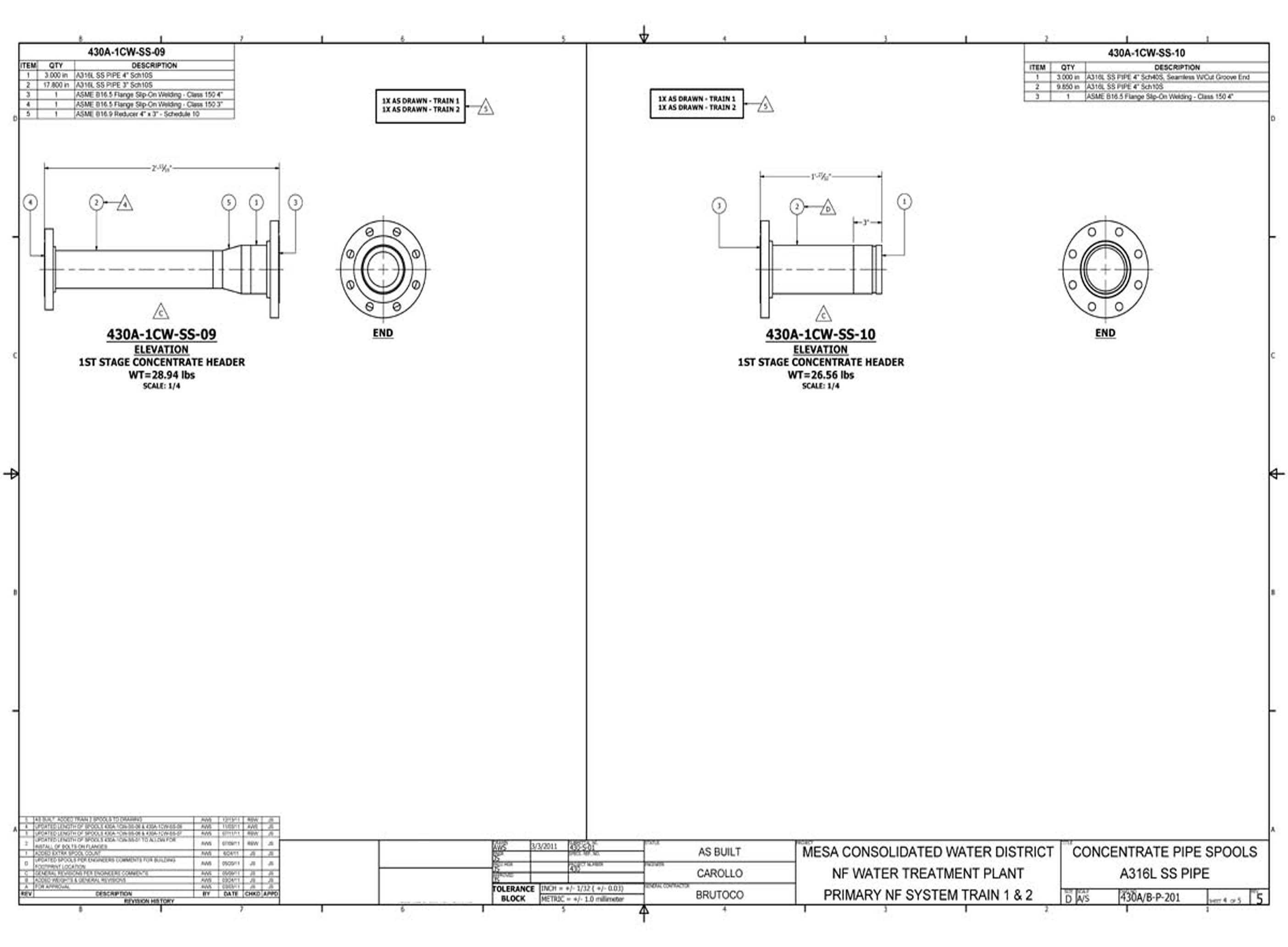
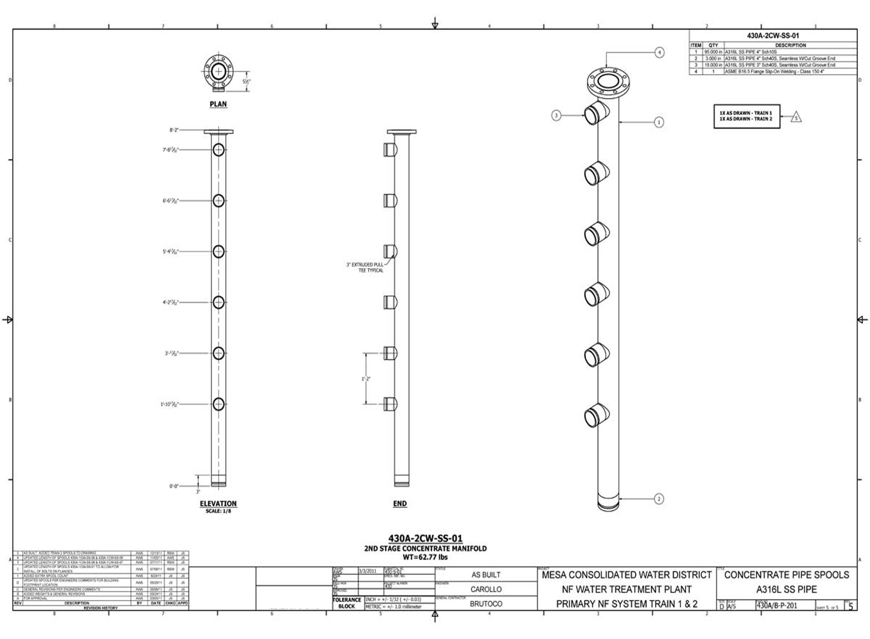
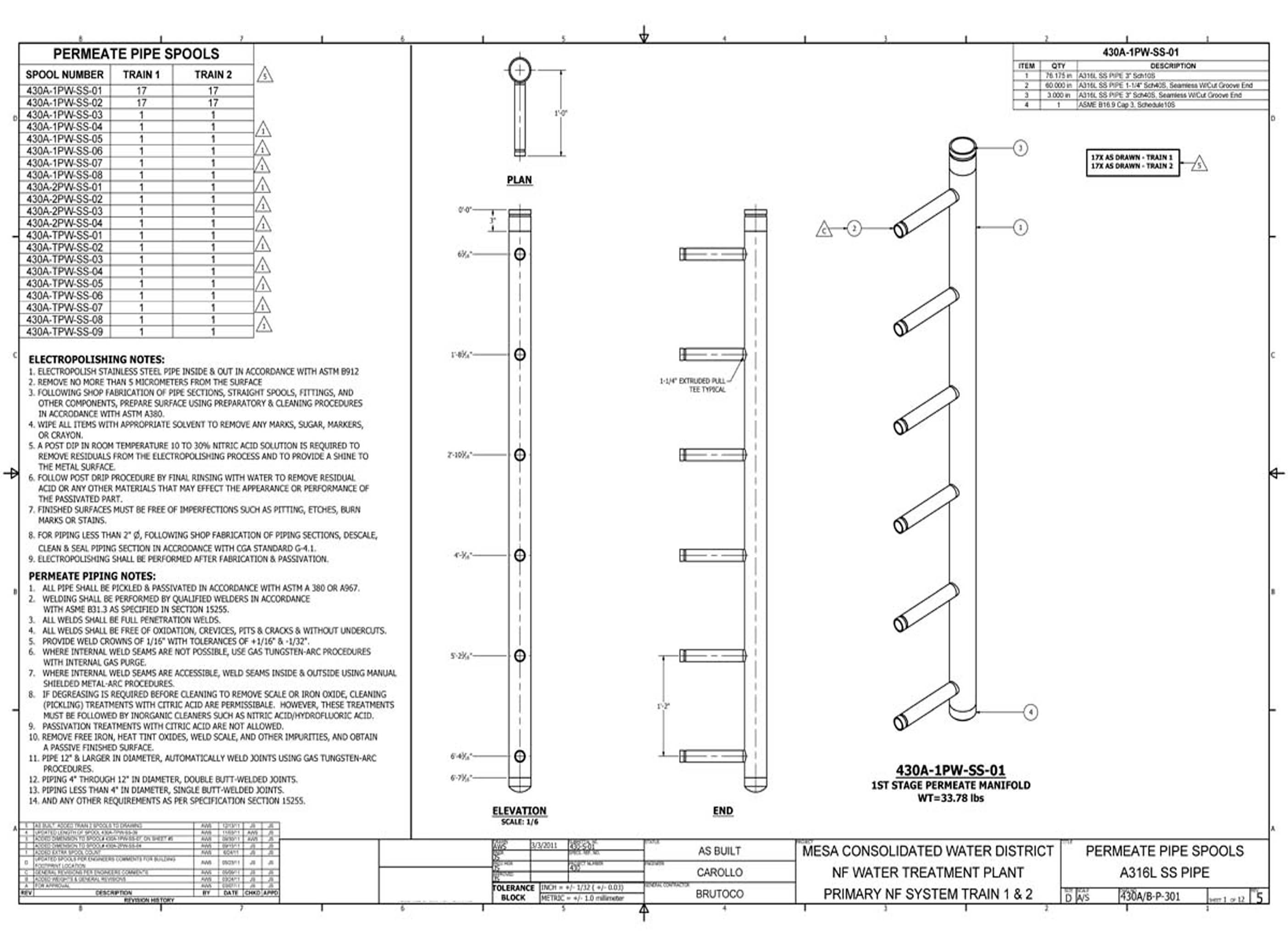
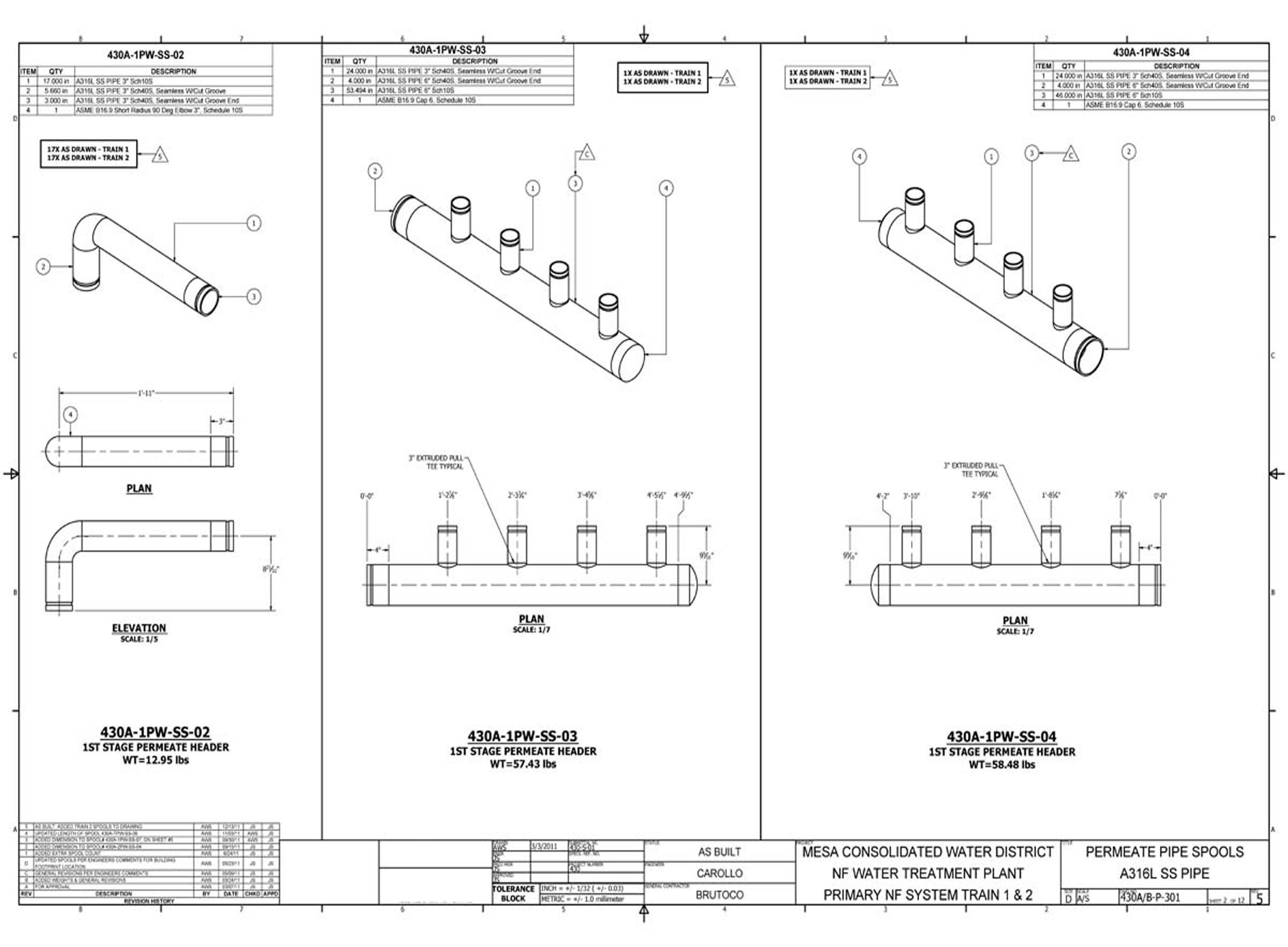
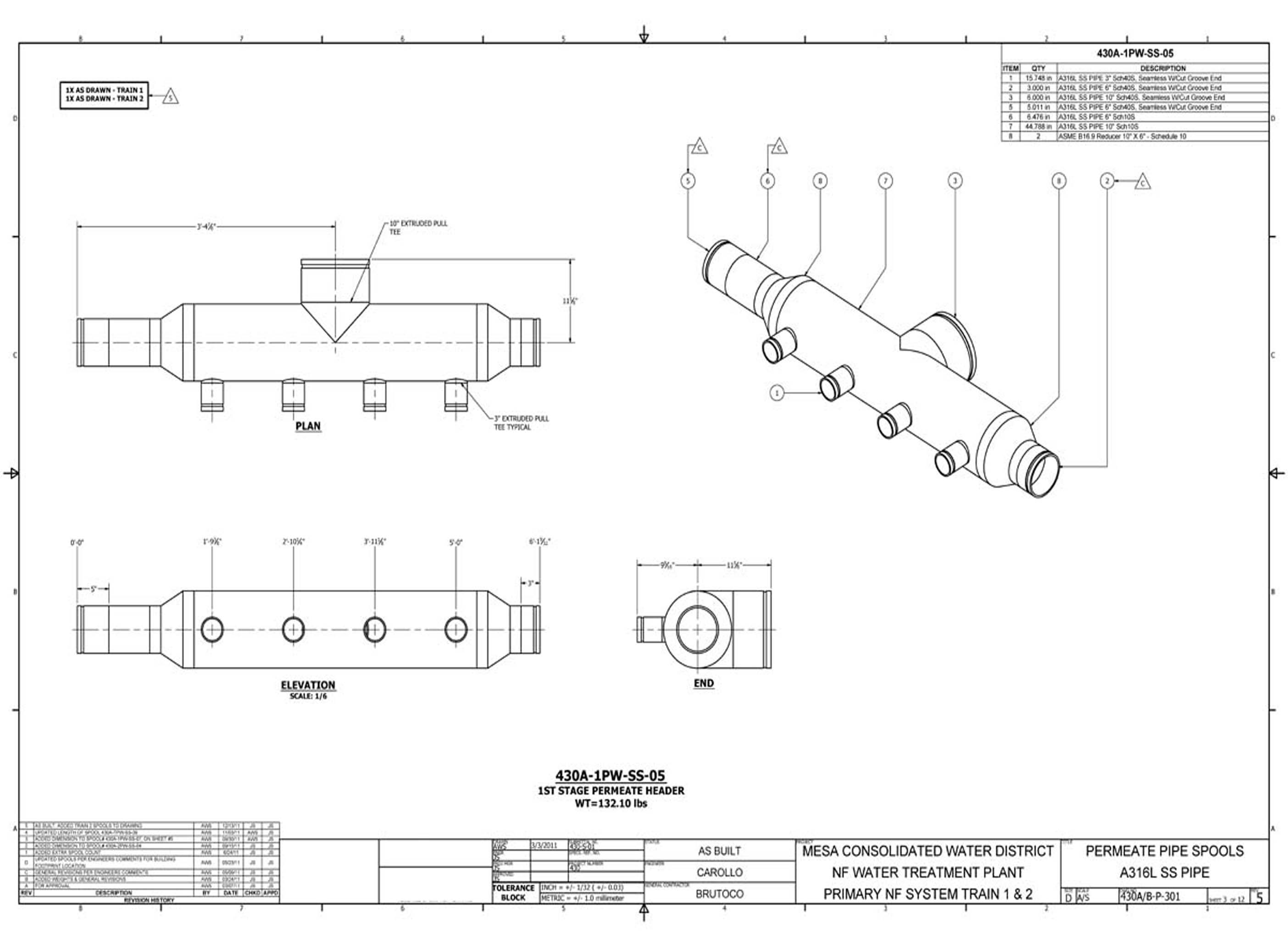
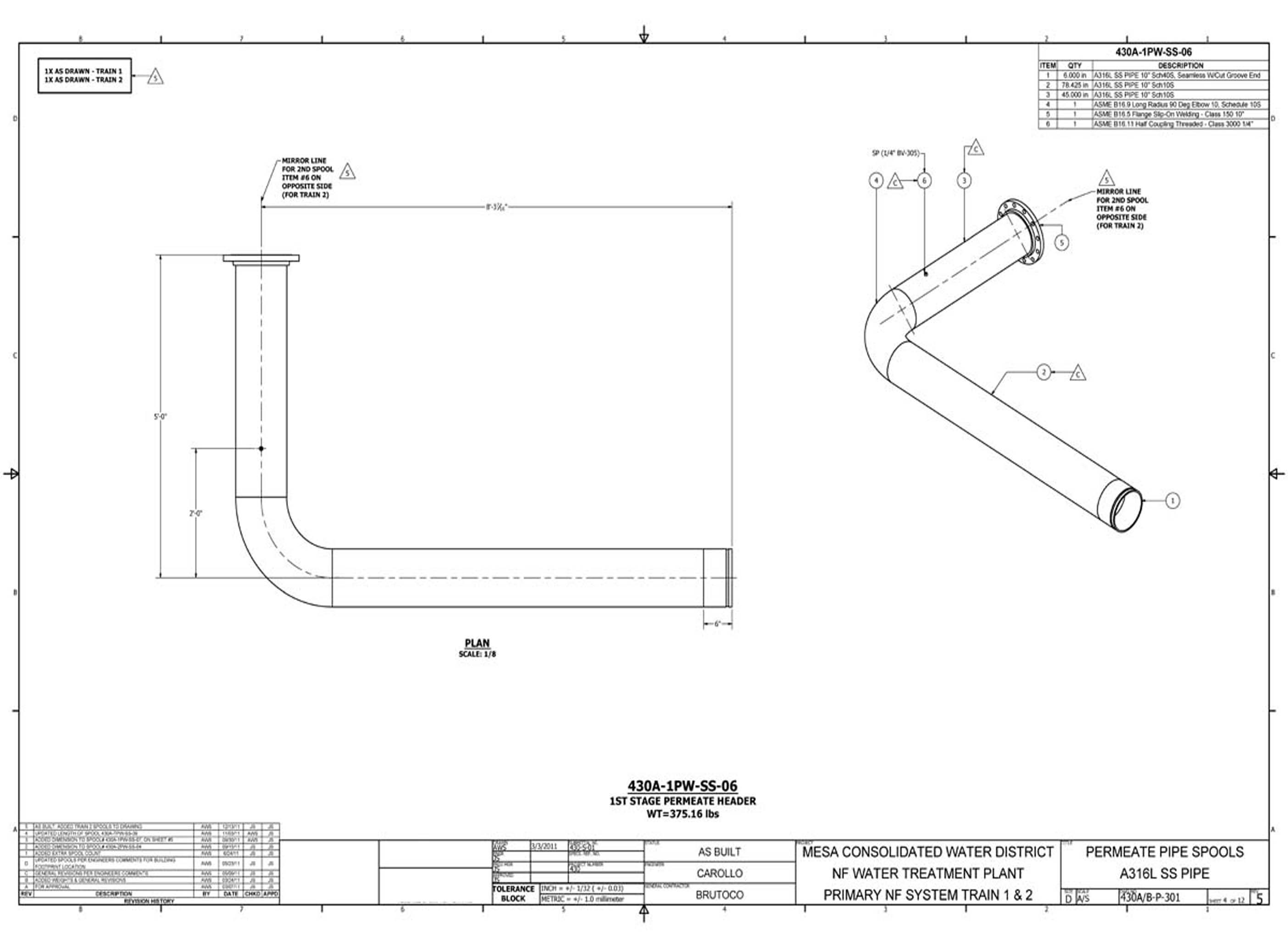
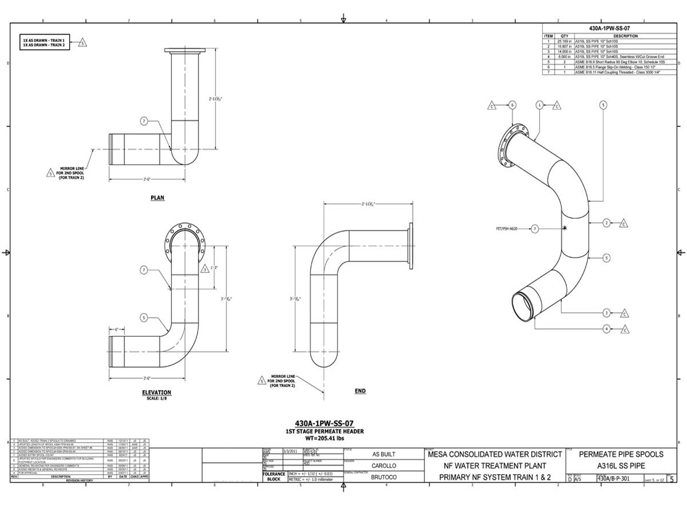
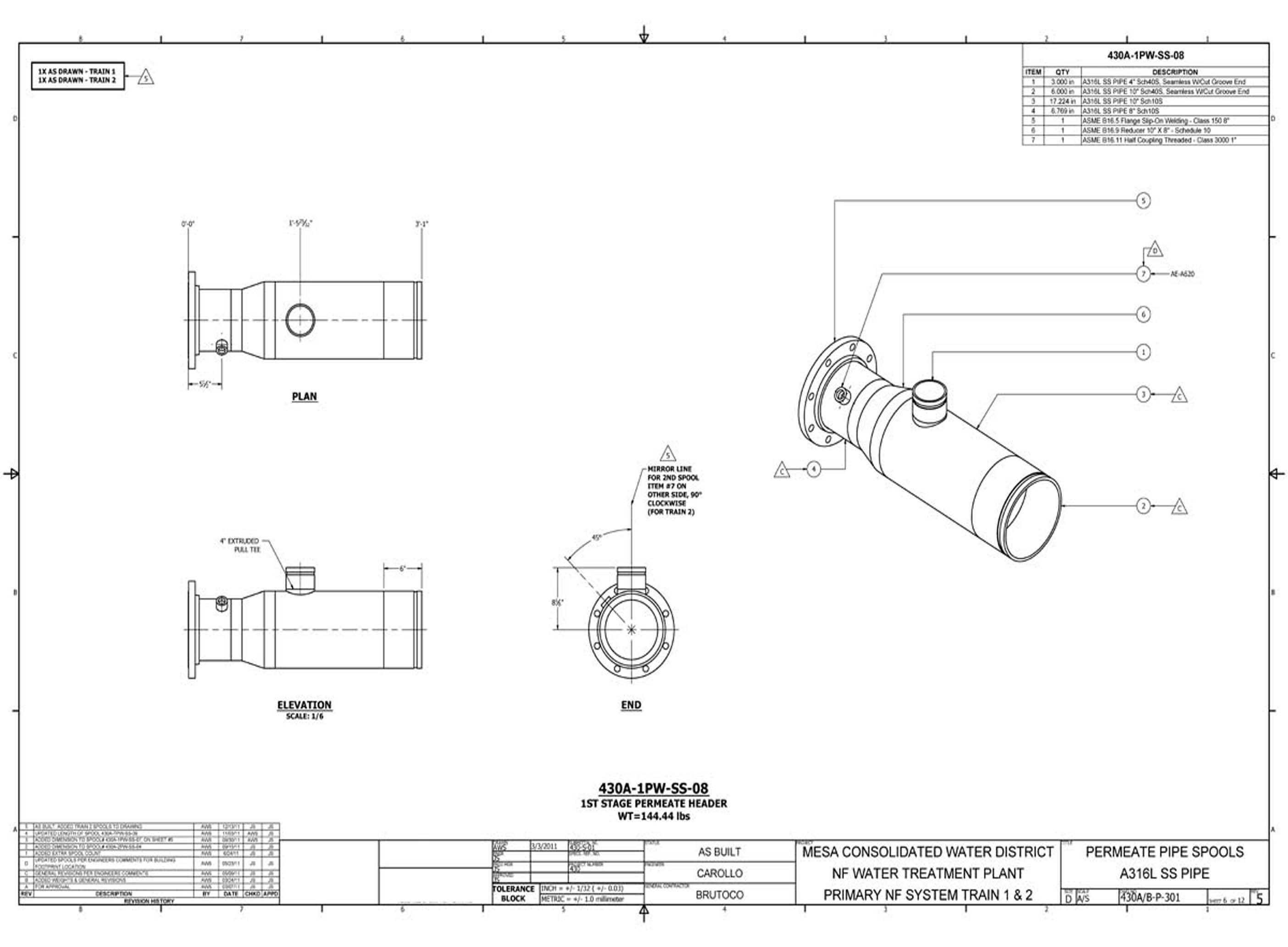
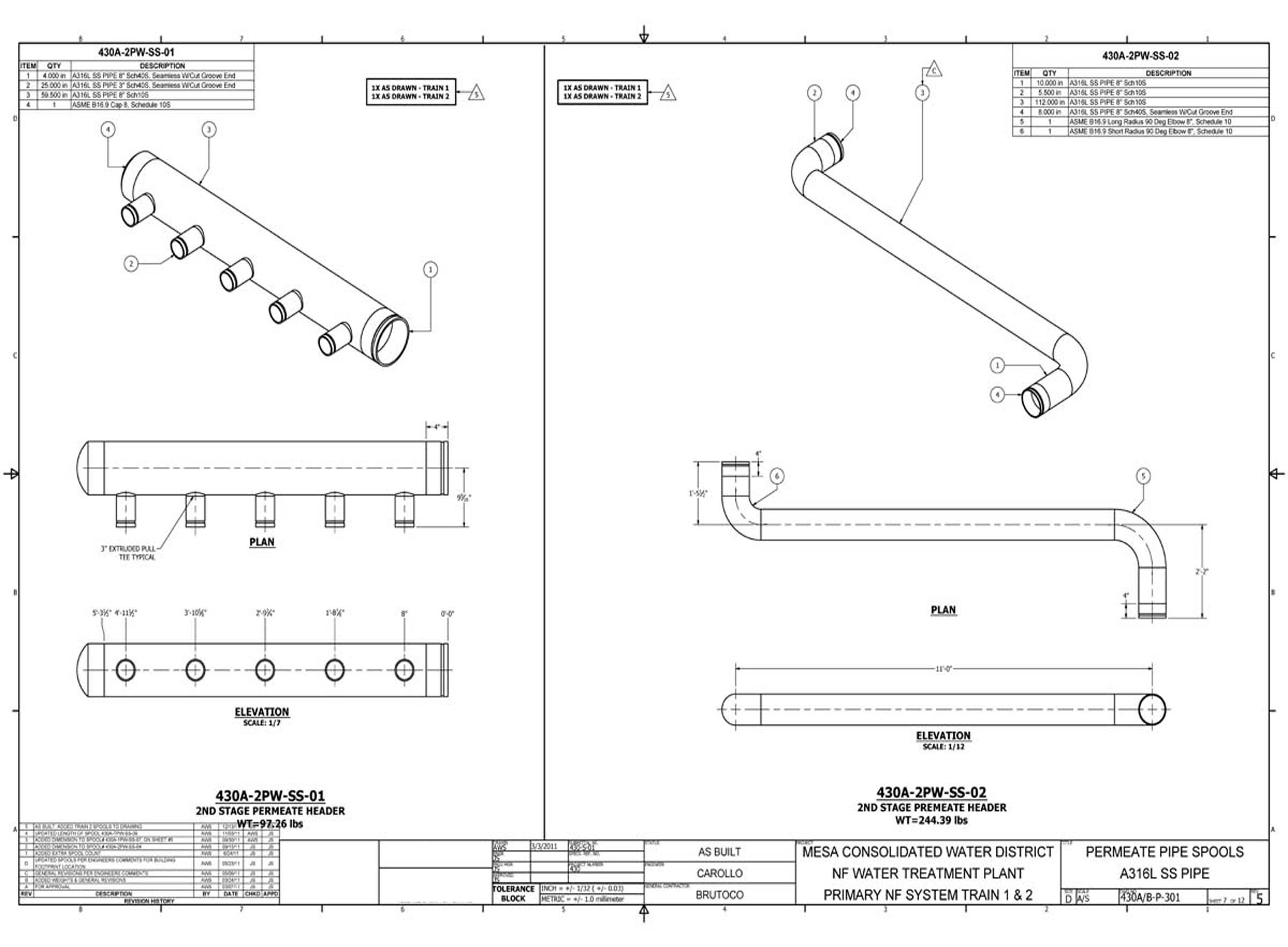
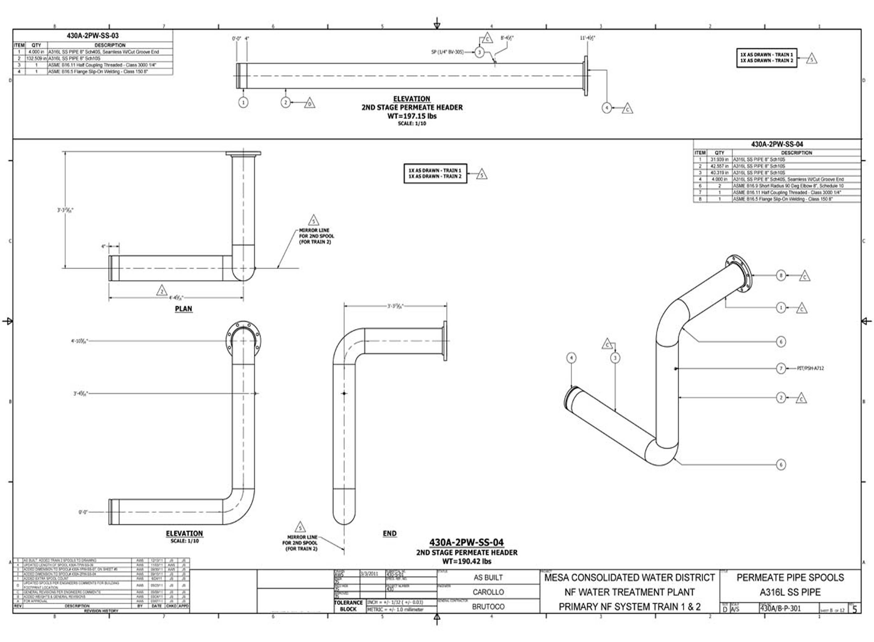
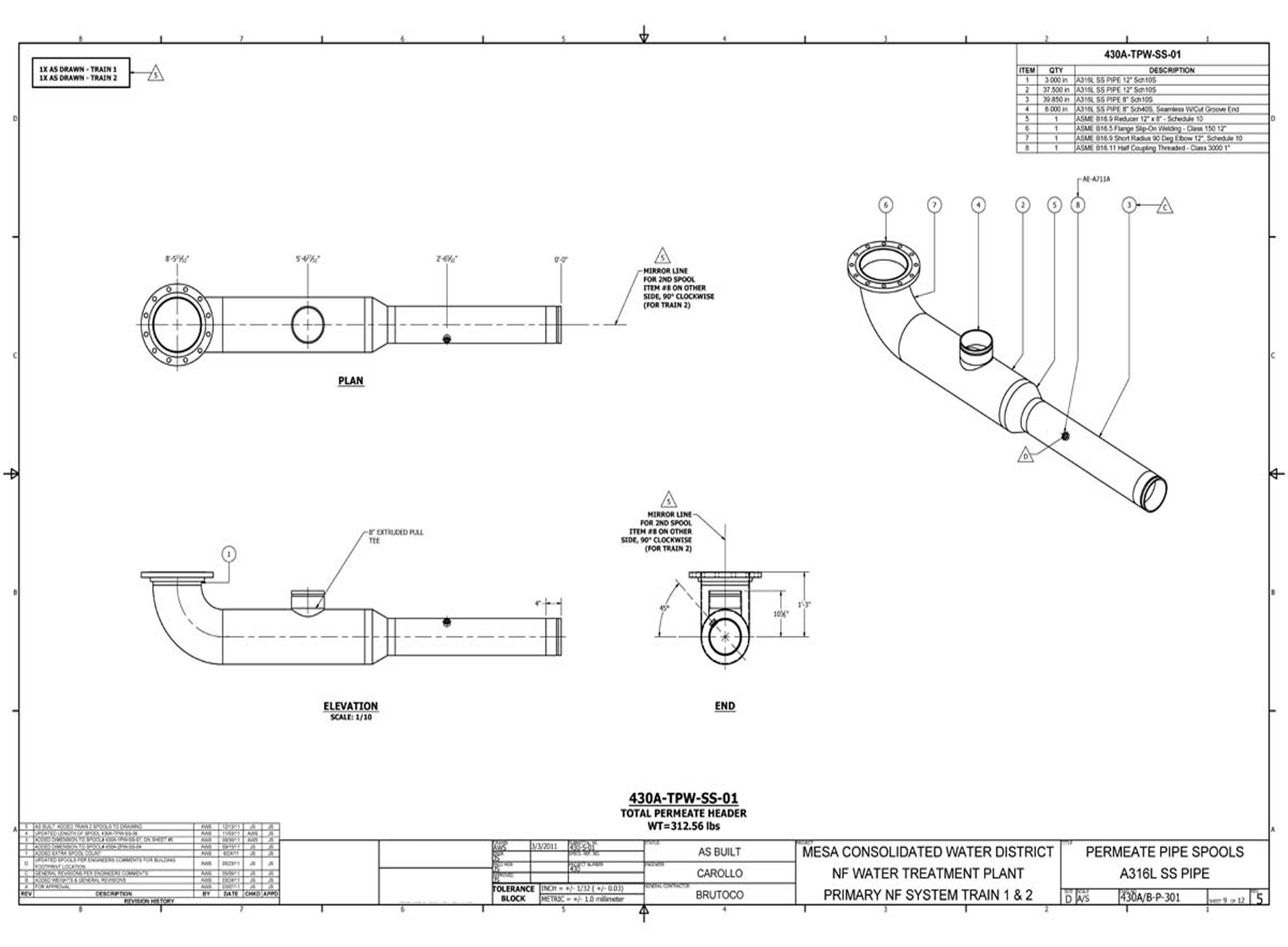
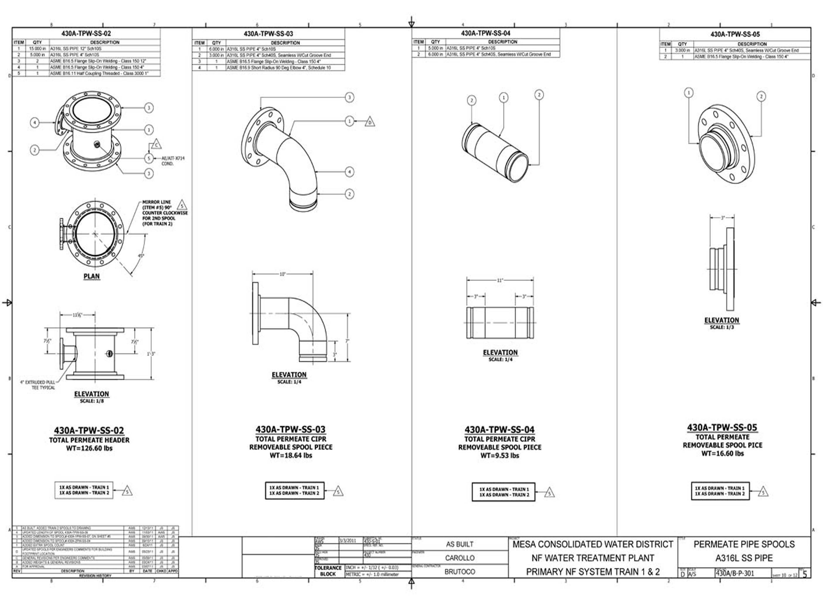
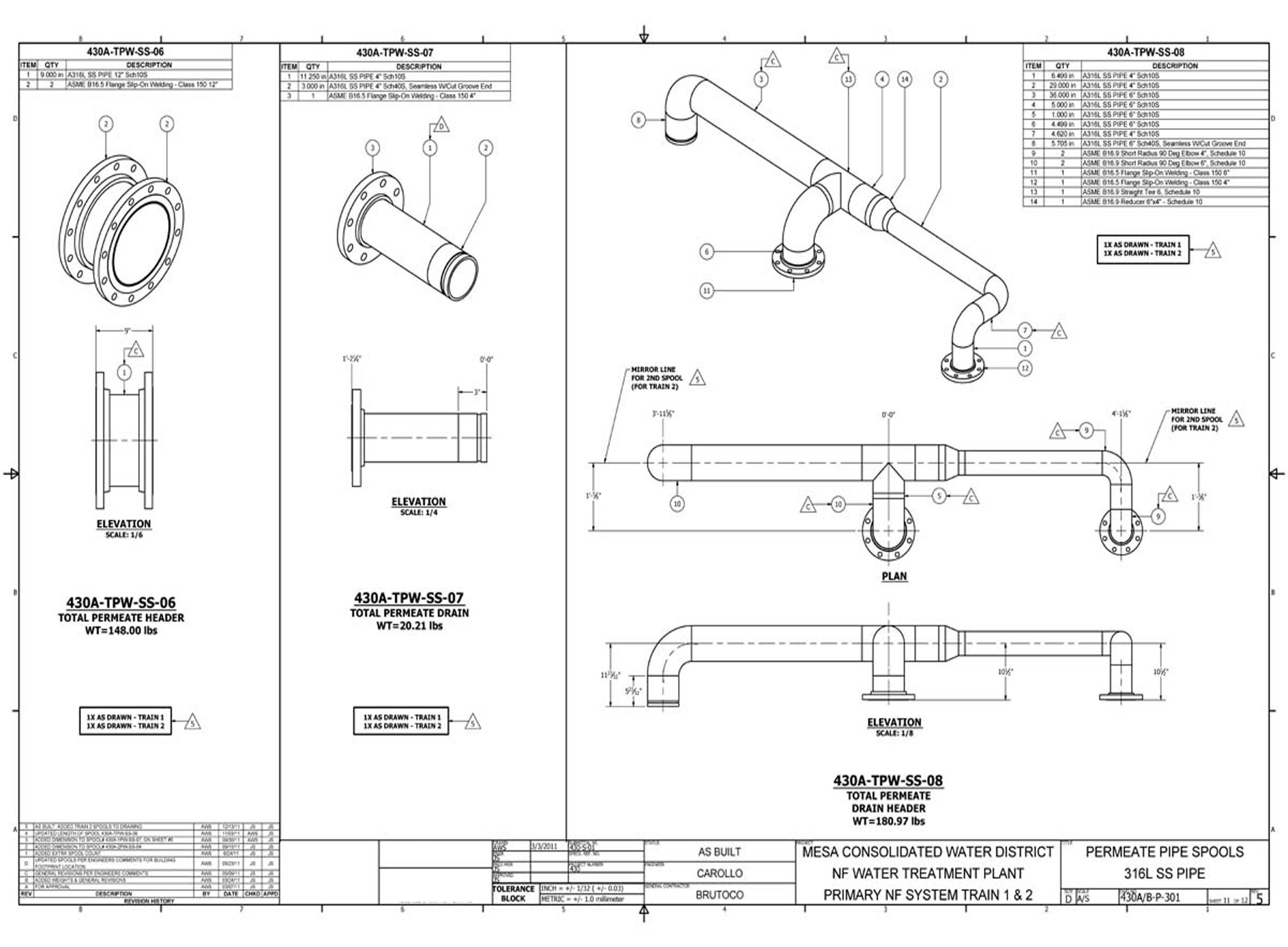
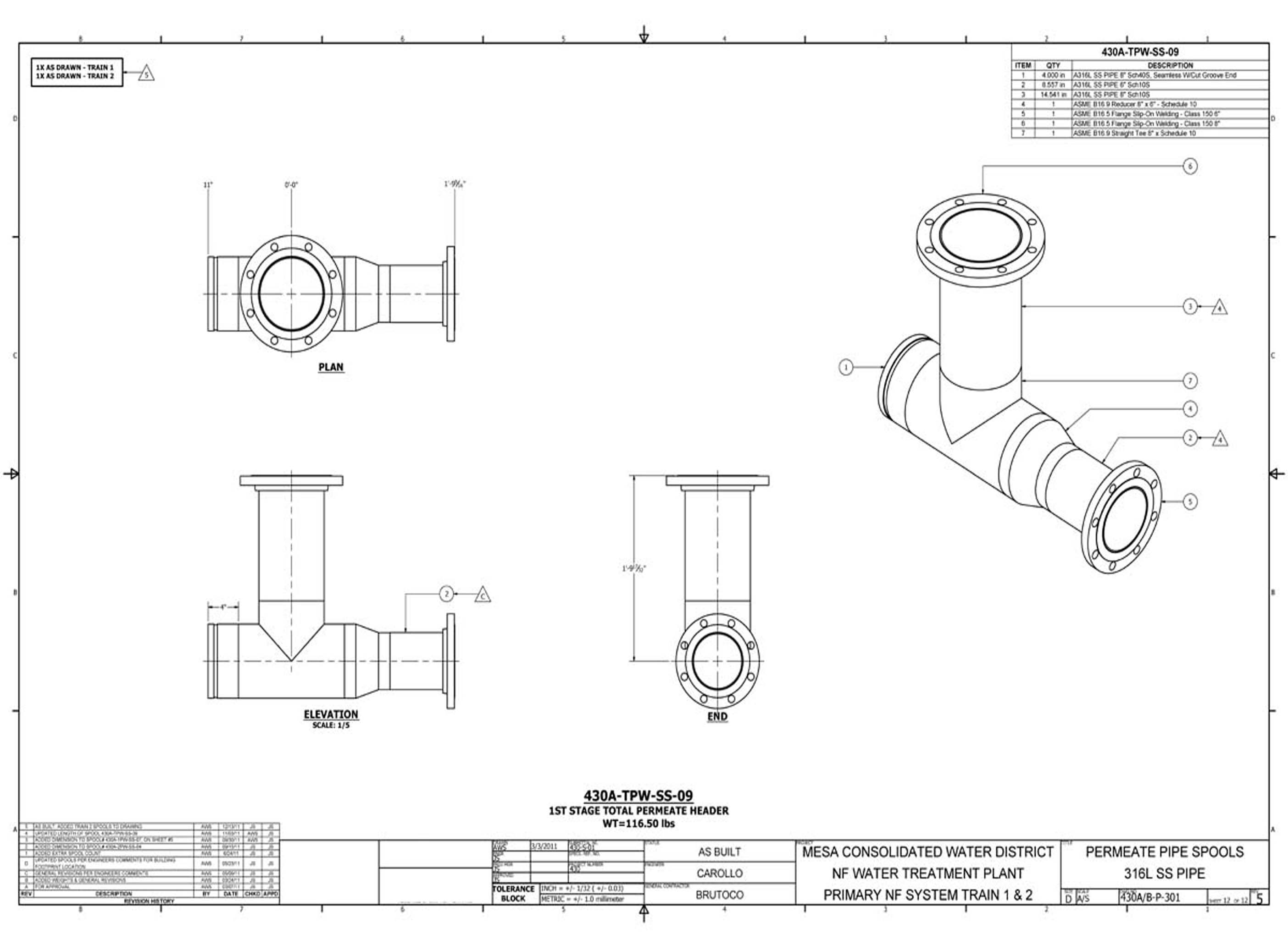
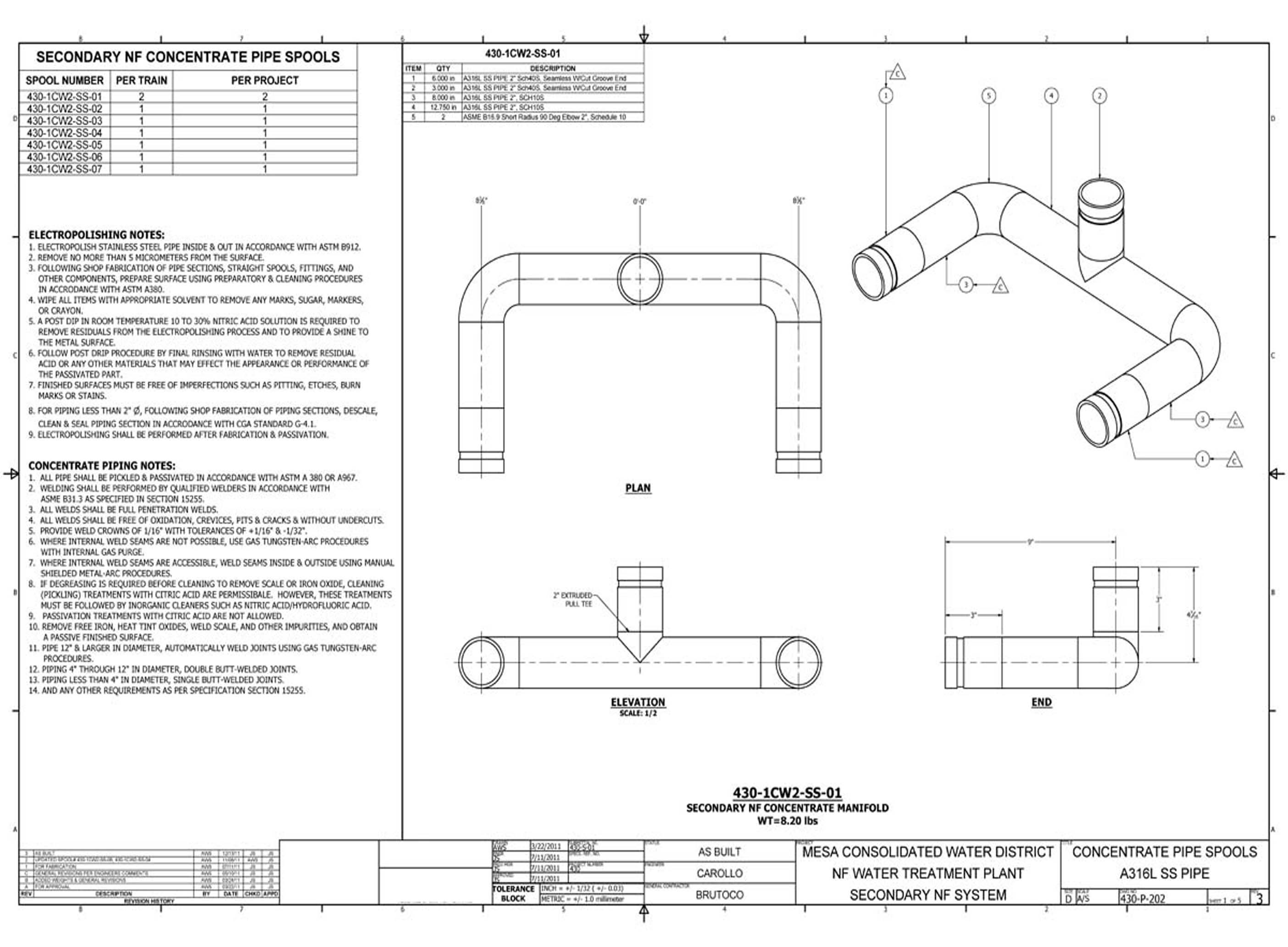
The 2nd System pipe spool drawings define the piping assemblies for the secondary process circuits at Costa Mesa. These 5 sheets cover the dimensional and welding specifications for the second-system piping components required for fabrication and field installation.
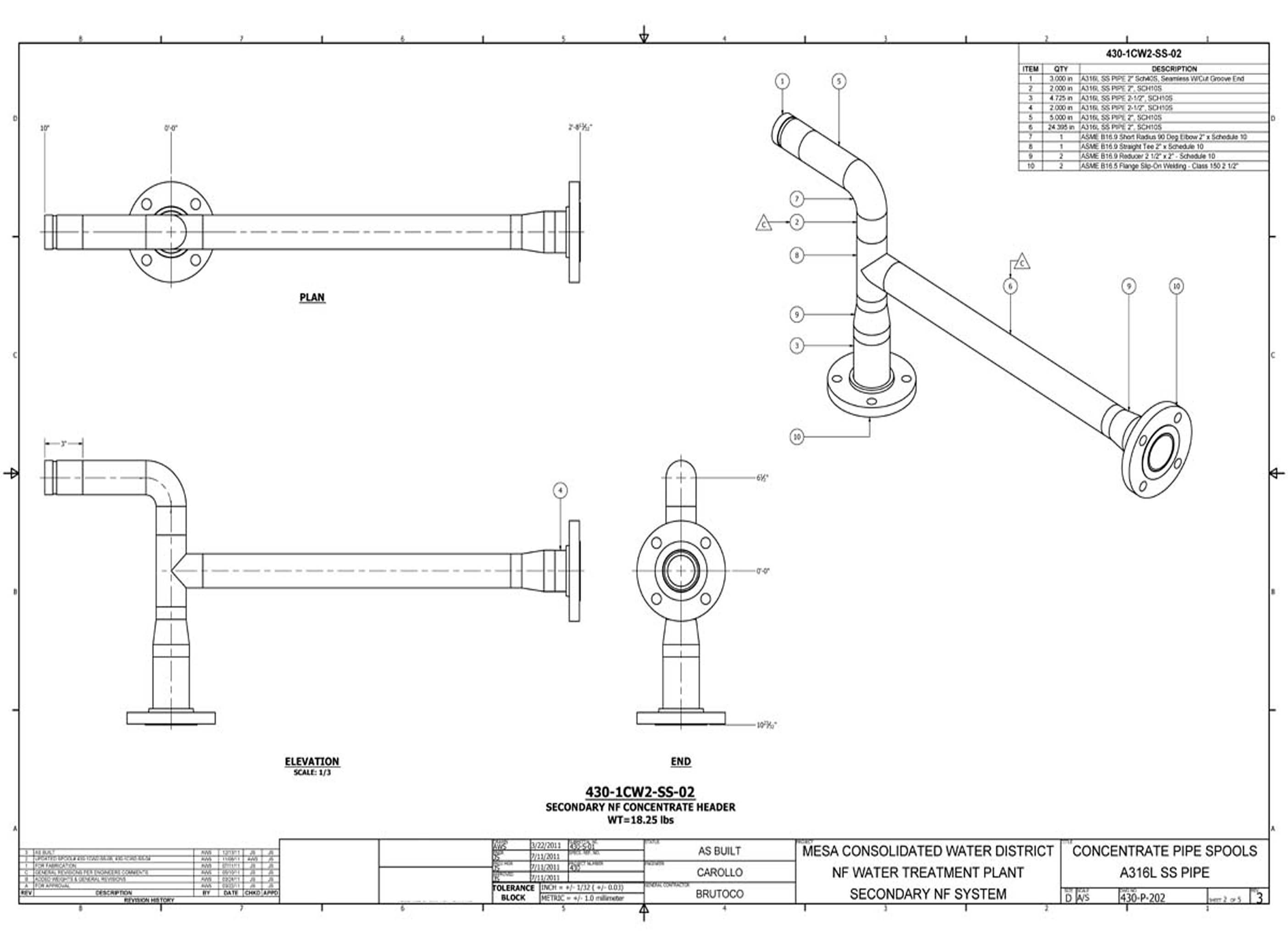
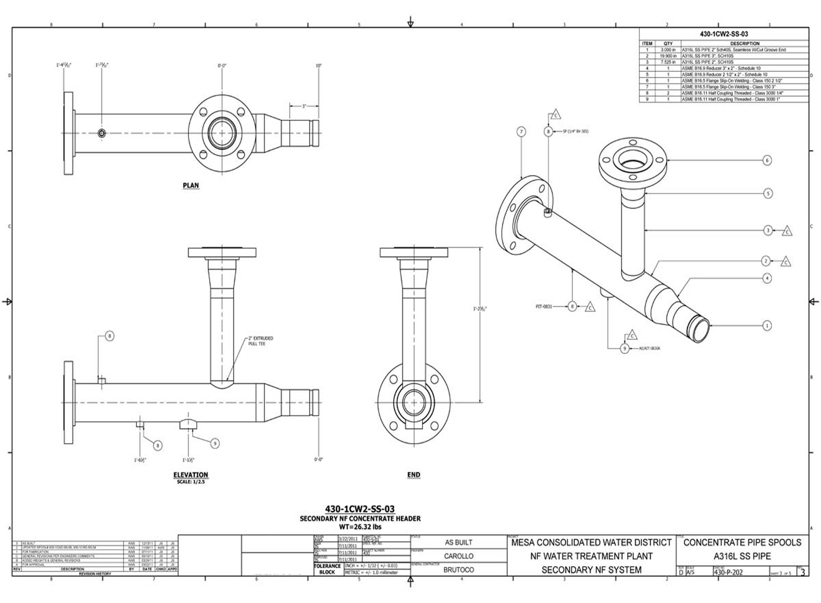
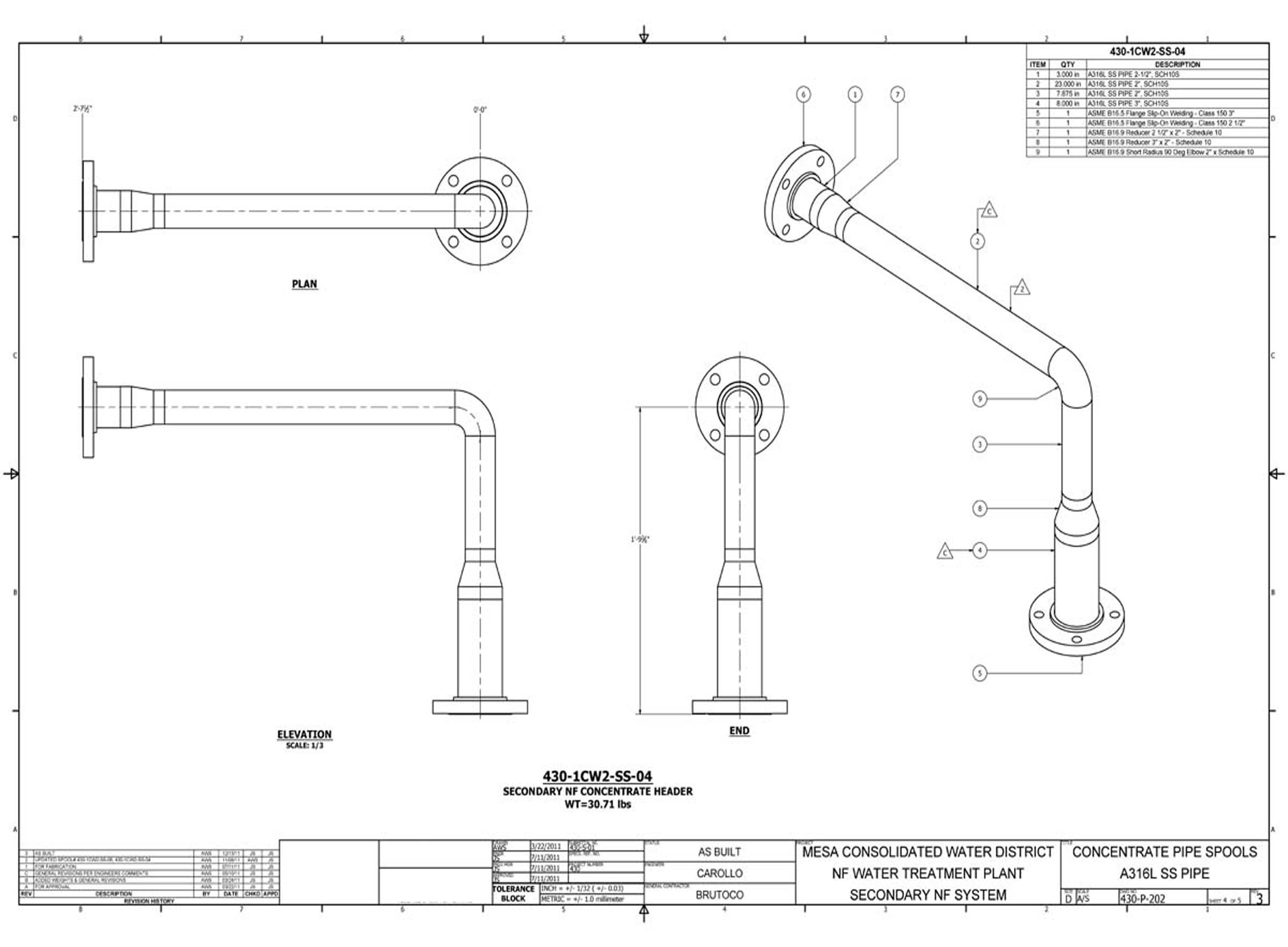
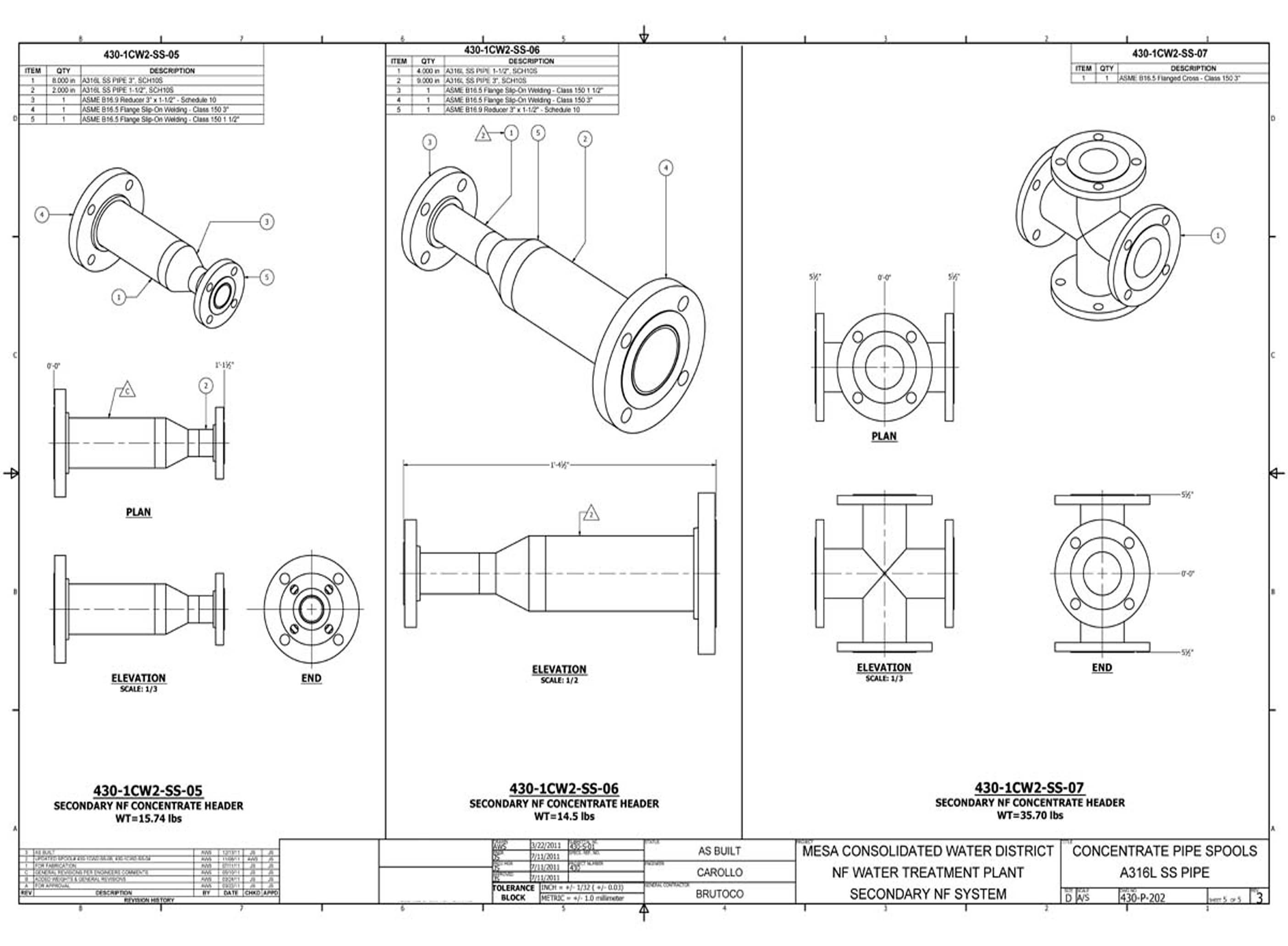
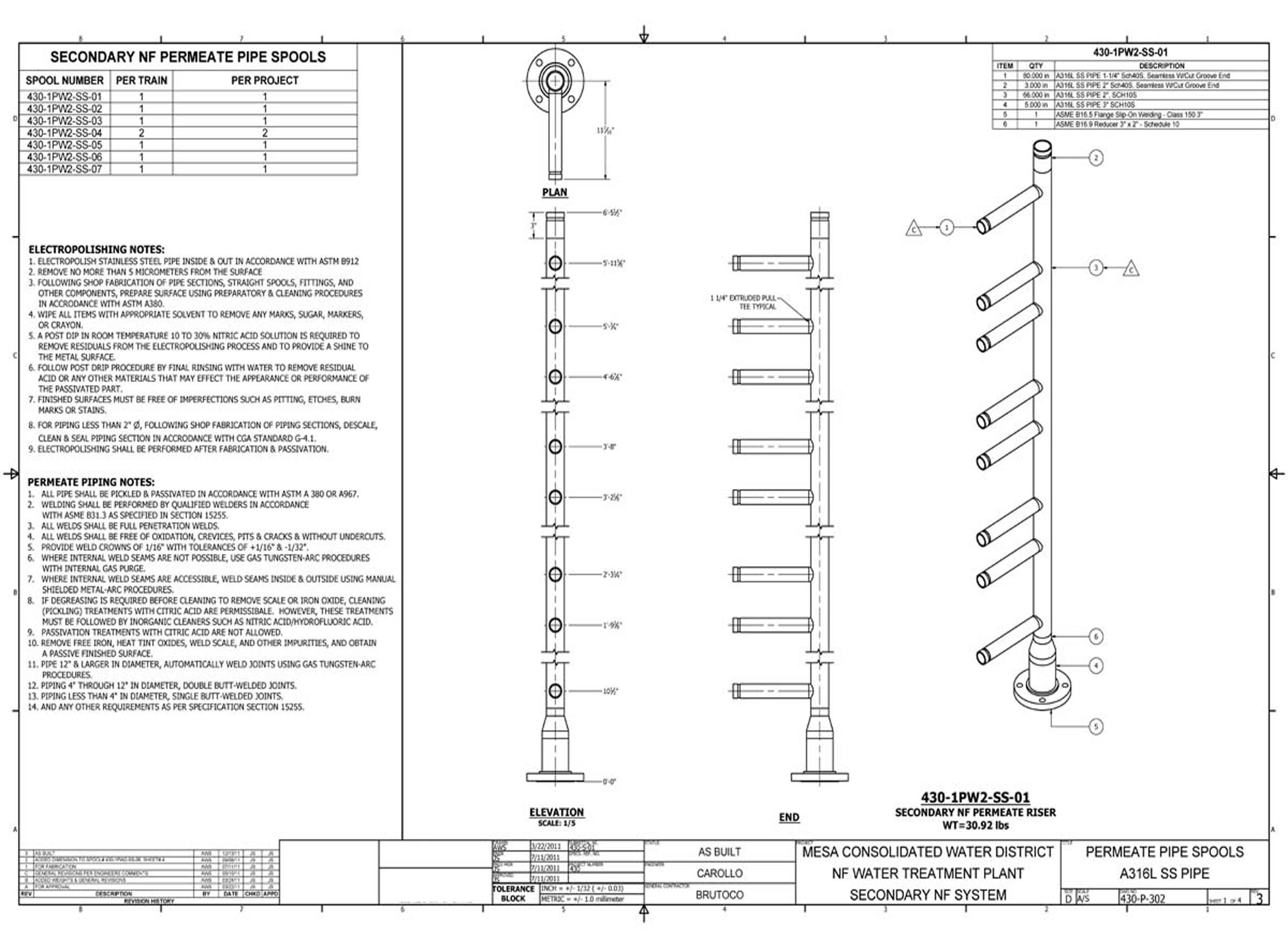
The NF System pipe spool drawings define the piping assemblies for the nanofiltration circuits at Costa Mesa. These 6 sheets document the NF skid interconnections, instrument connections, and spool dimensional data required for shop fabrication and installation of the NF process piping.
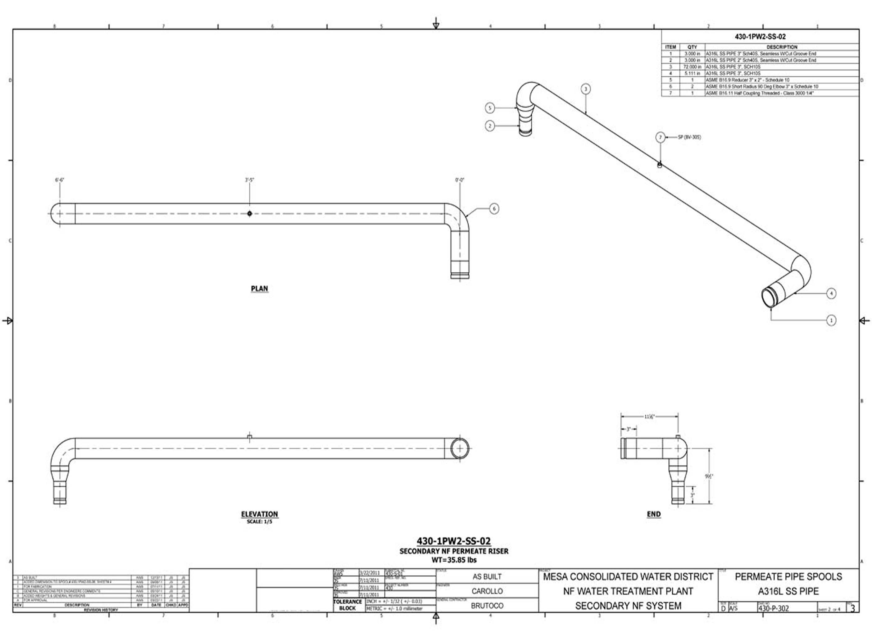
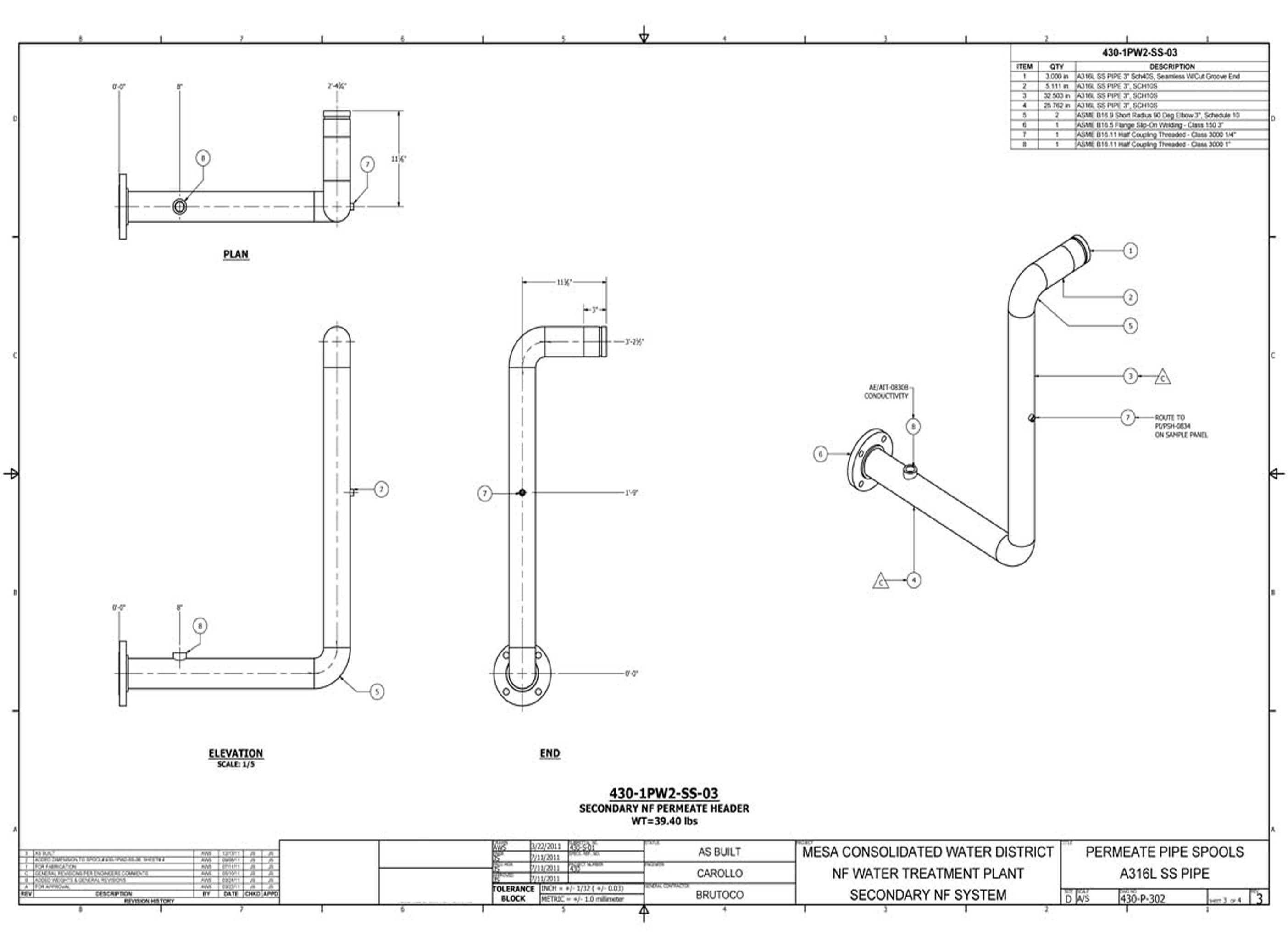
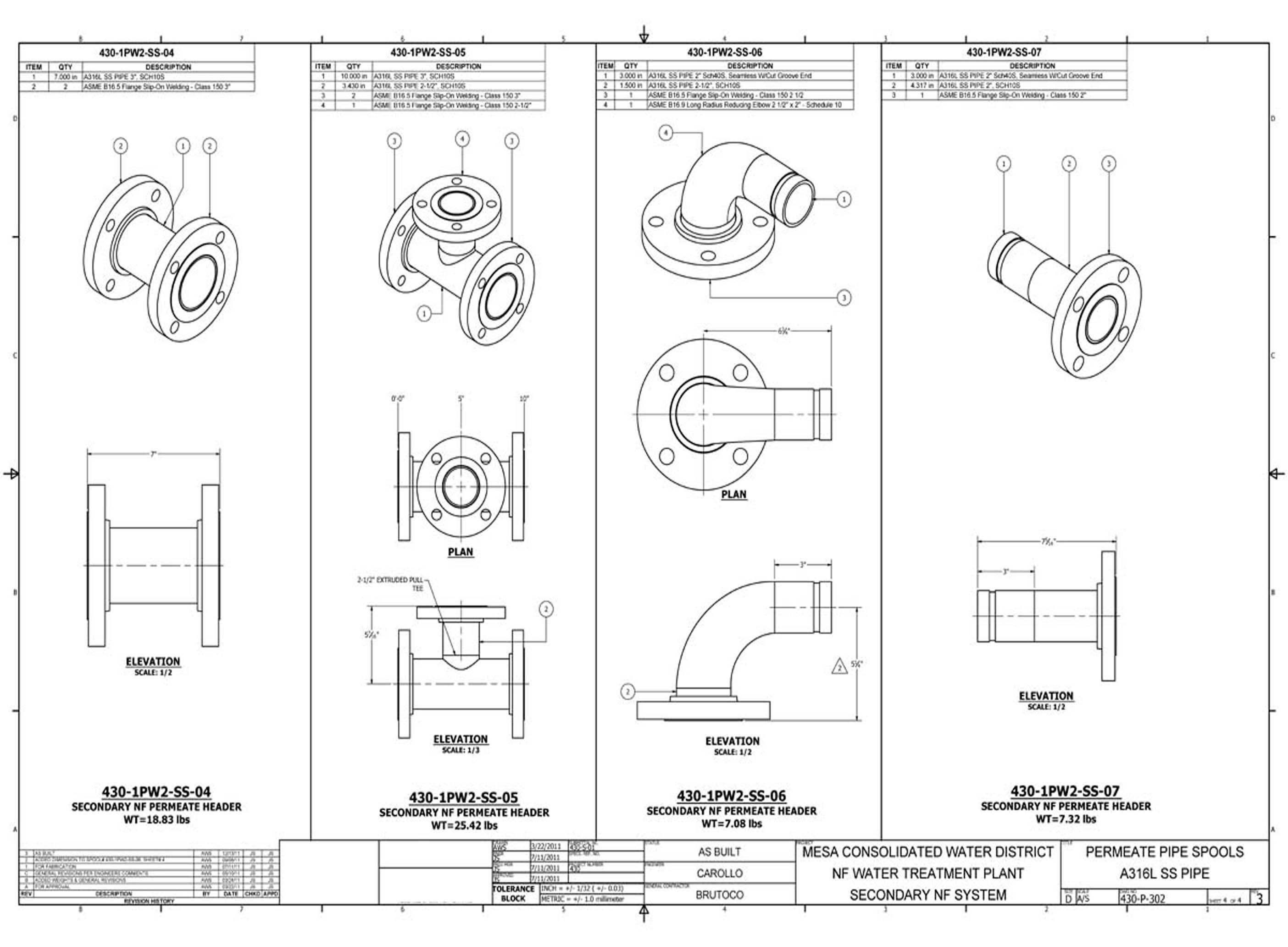
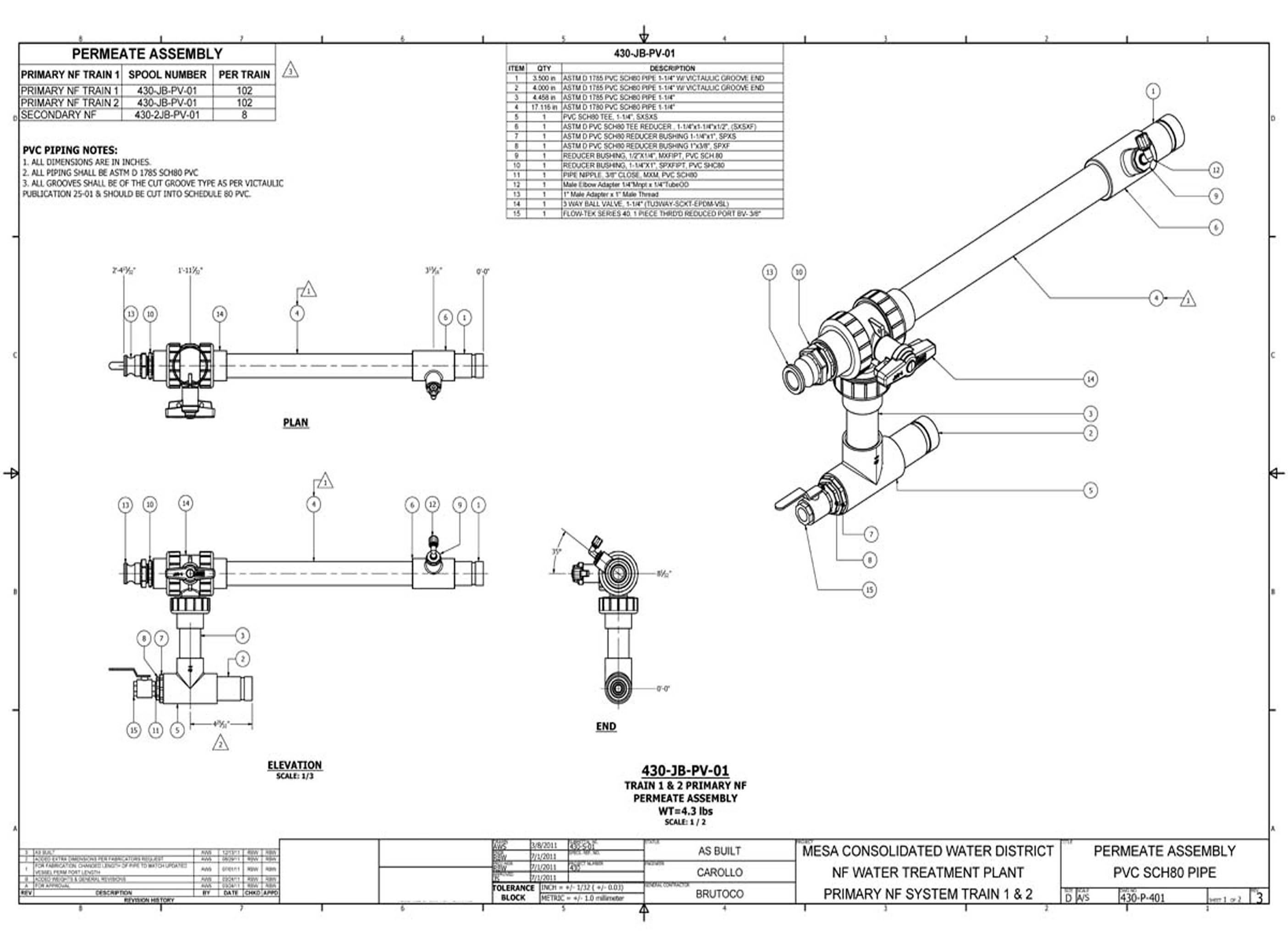
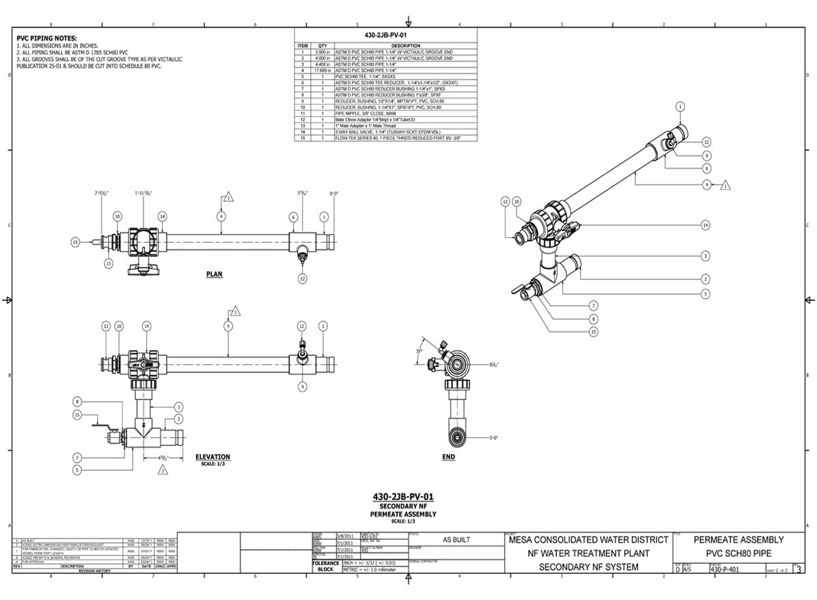
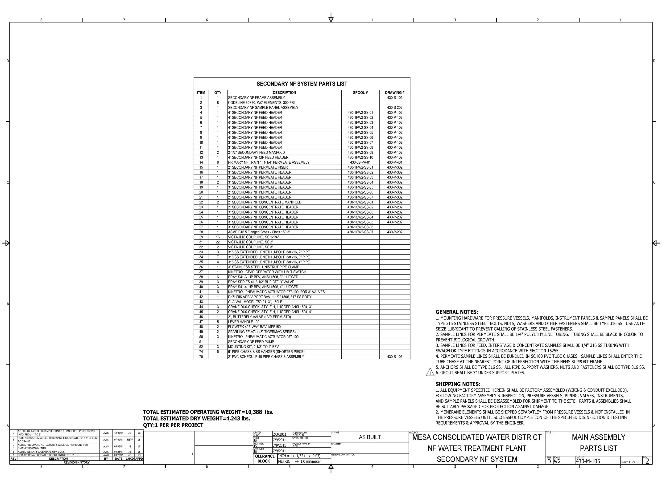
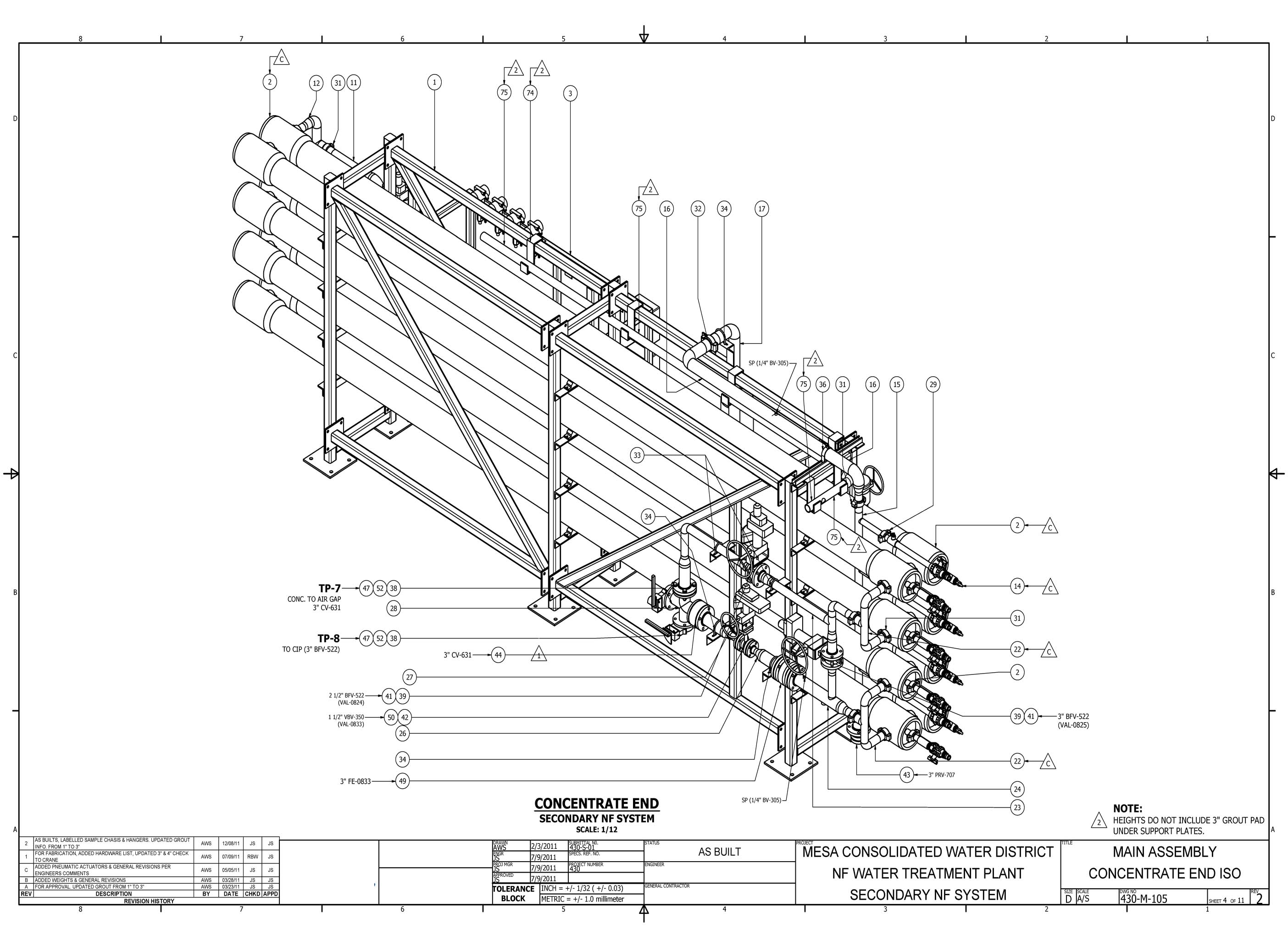
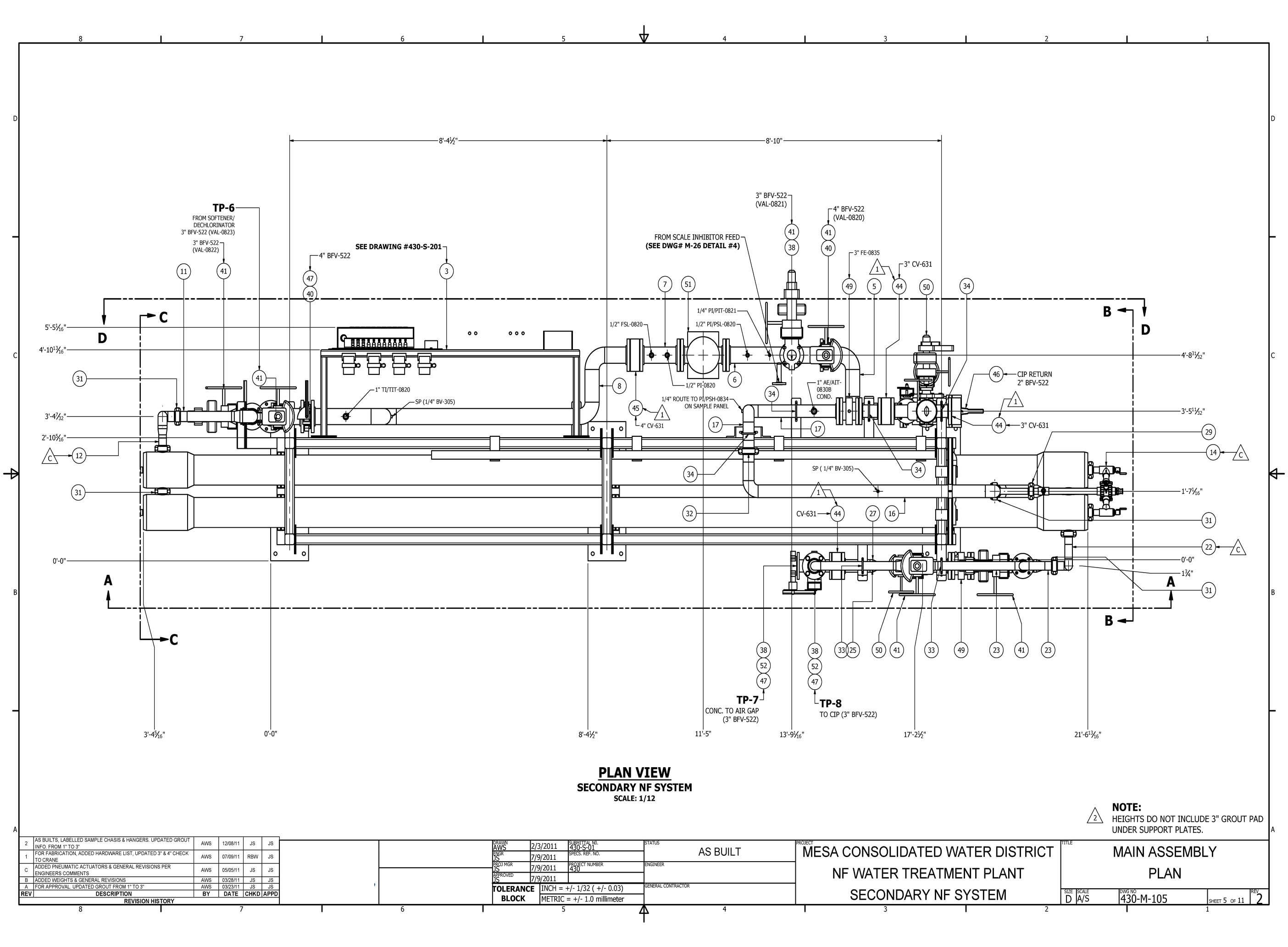
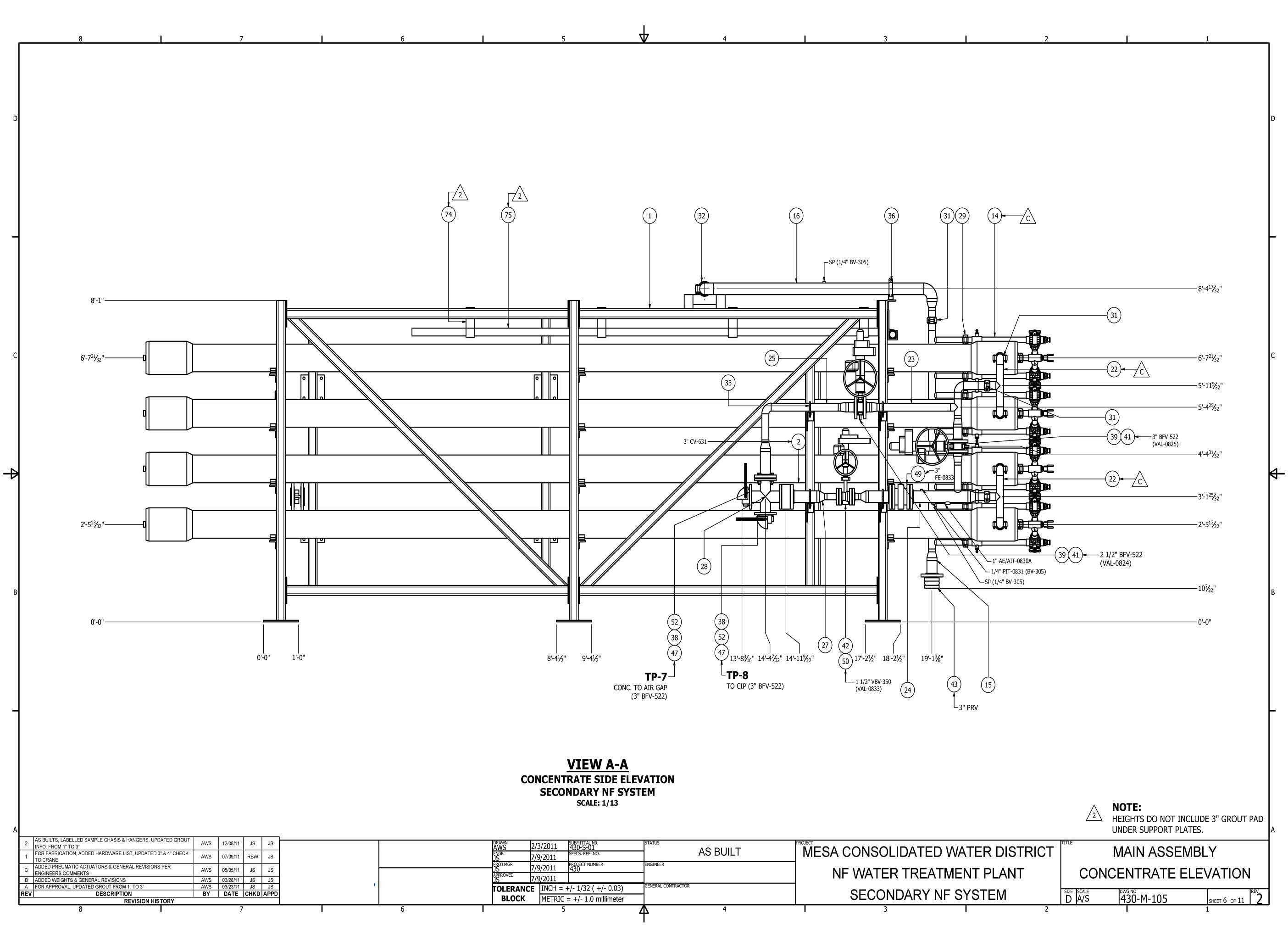
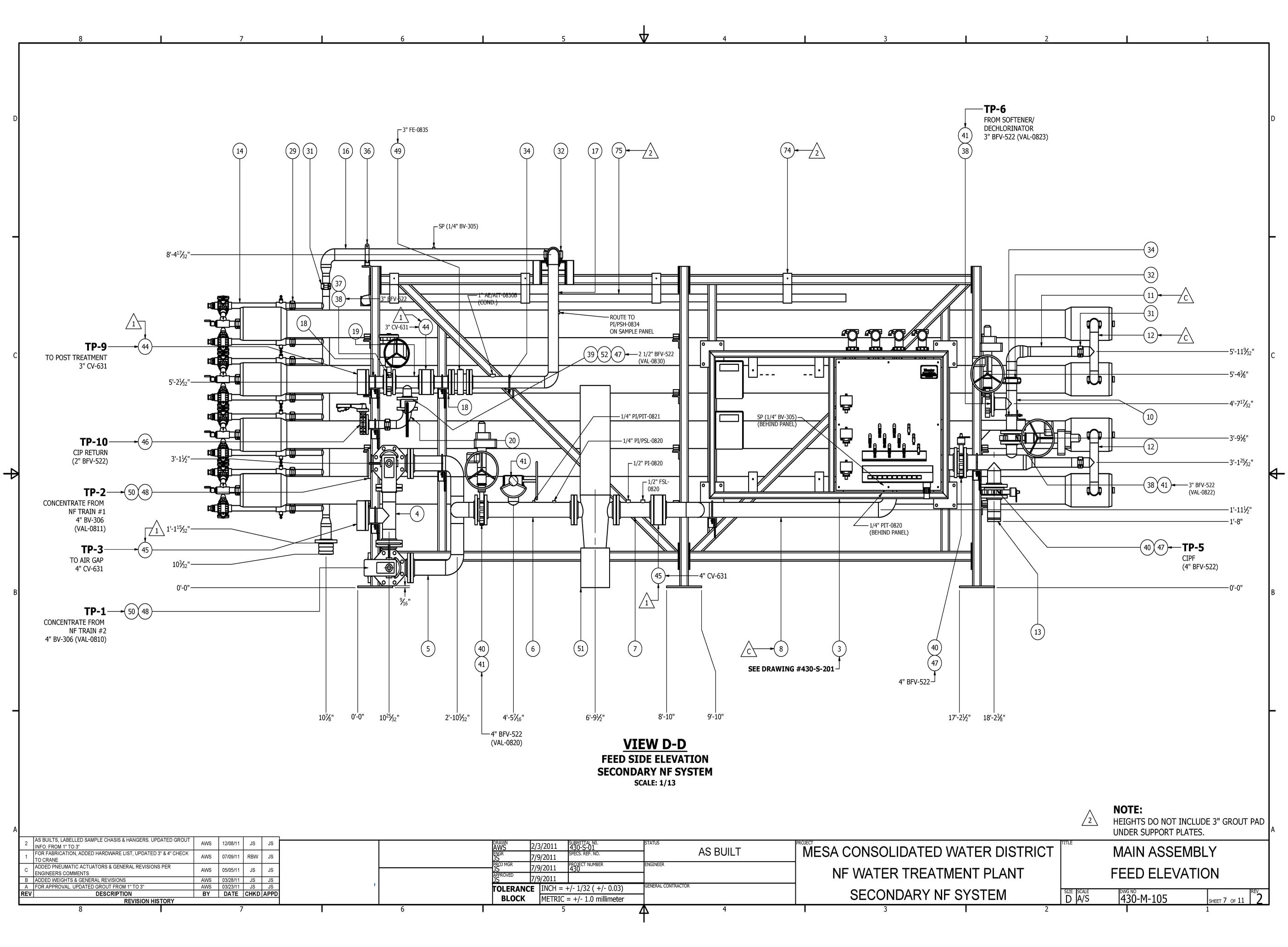
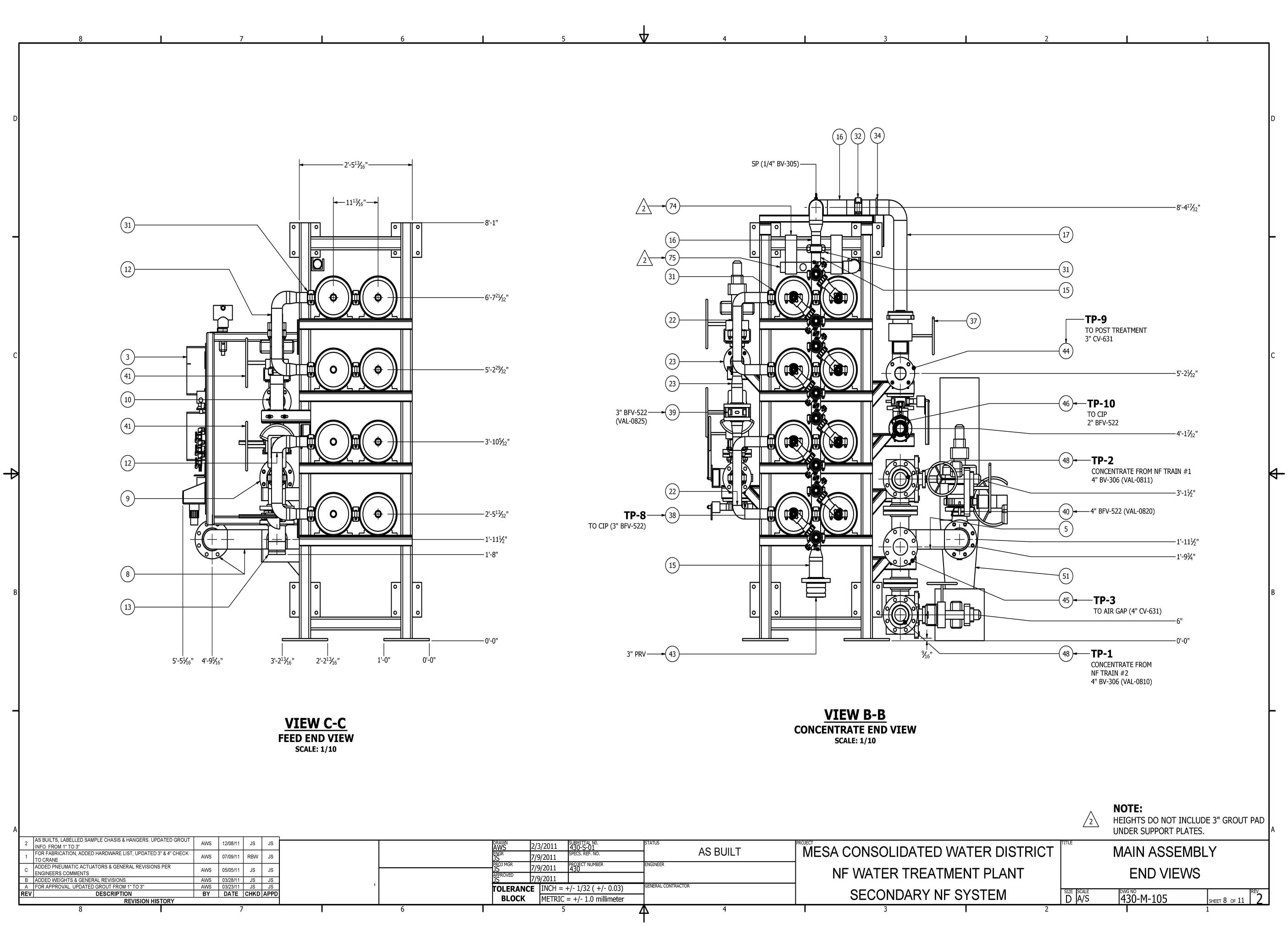
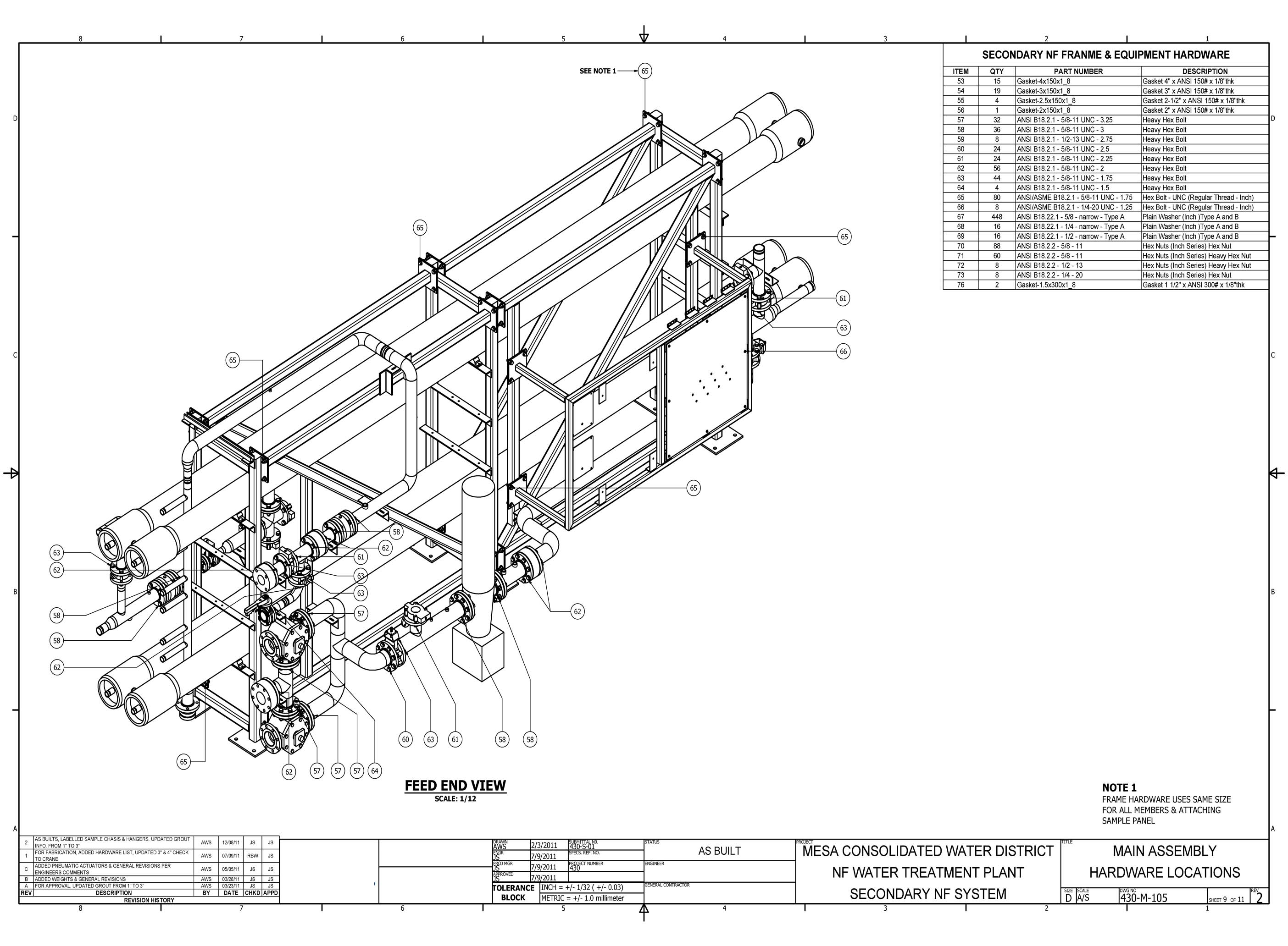
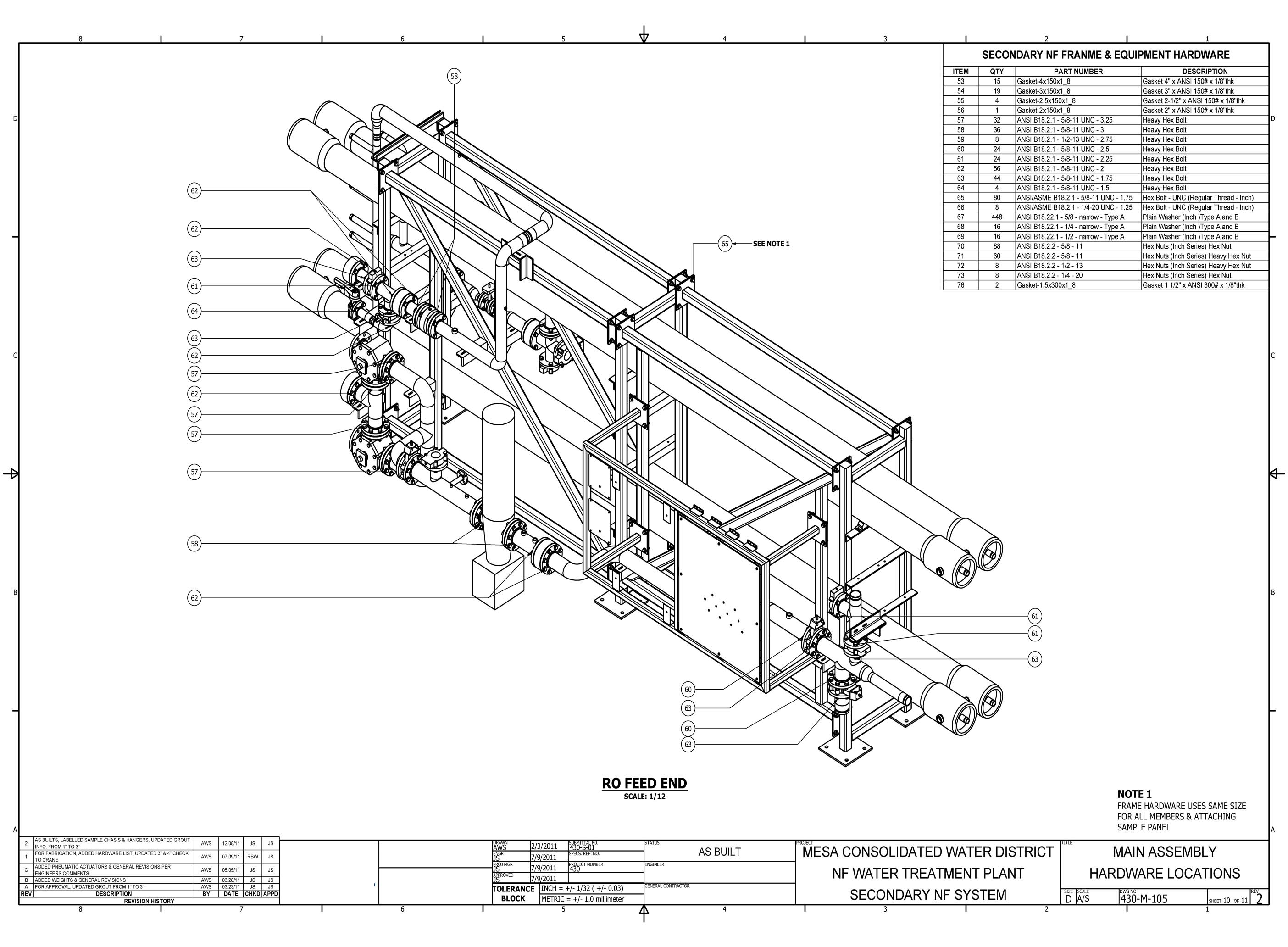
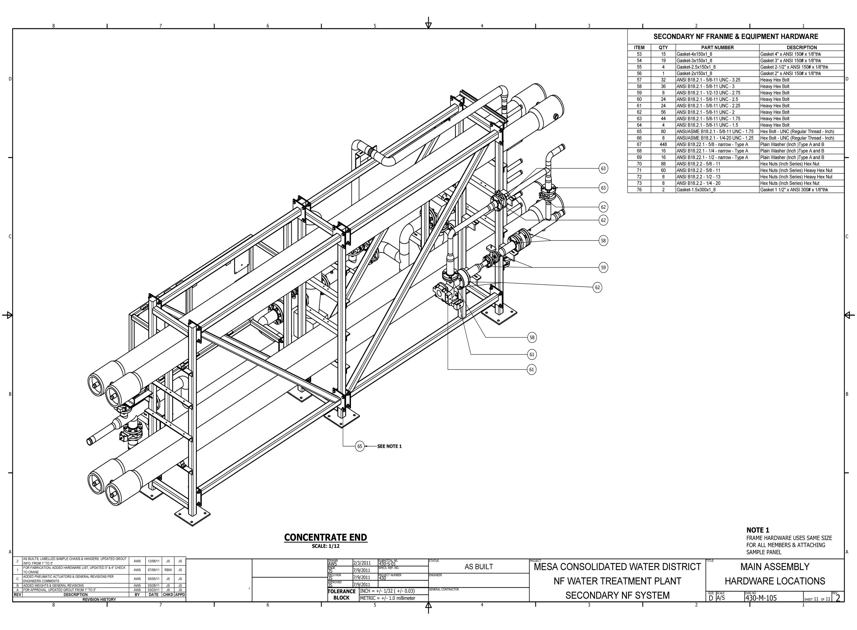
The NF System General Detail drawings document the overall configuration, equipment layout, and connection details for the nanofiltration treatment stage at Costa Mesa. These 11 sheets provide the system-level reference for the NF skid assembly, instrument placement, and process flow routing.
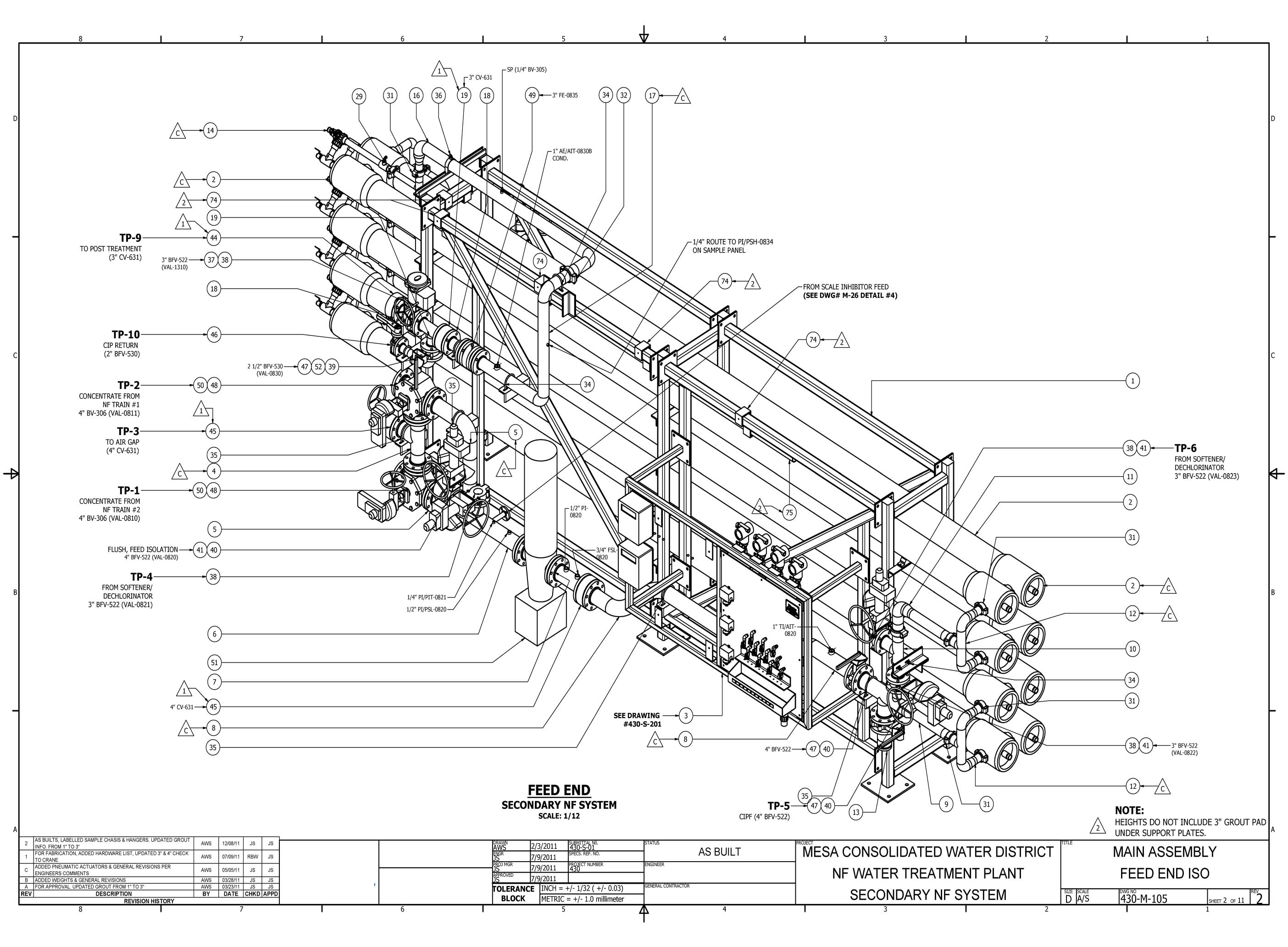
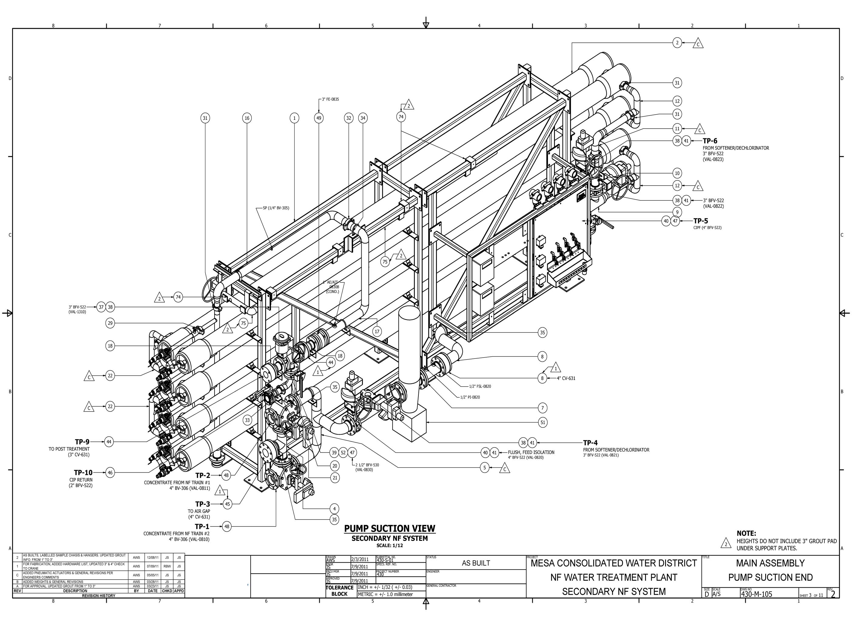
These interactive models were built in Autodesk Inventor and published to Sketchfab. Click and drag to orbit, scroll to zoom, right-click to pan. Models are real-scale and accurate to the fabrication drawings in this set.